EasyManua.ls Logo

Lenze ECS series User Manual

Lenze ECS series
483 pages
To Next Page IconTo Next Page
To Previous Page IconTo Previous Page
Page #158 background imageLoading...
Page #158 background image
System bus (CAN / CAN−AUX) configuration
Setting the CAN node address and baud rate
Settings via codes
8
158
EDBCSXA064 EN 3.2
8.1.2 Settings via codes
Note!
ƒ The settings in C0350/C2450 (CAN node address) and C0351/C2451 (baud
rate) are only used if the (address) switches 2 ... 7 of the DIP switch S1 are
switched off (OFF).
ƒ If only one (address) switch 2 ... 7 is switched on (ON), the settings of the DIP
switch S1 usually apply.
ƒ The baud rate (C0351/C2451) must be set identically for all CAN bus nodes.
ƒ If the Lenze setting has been loaded via C0002,
C0351/C2451 is set = 0 (500 kbits;
you have to reset the baud rate (C0351/C2451) and the CAN node address
(C0350/C2450).
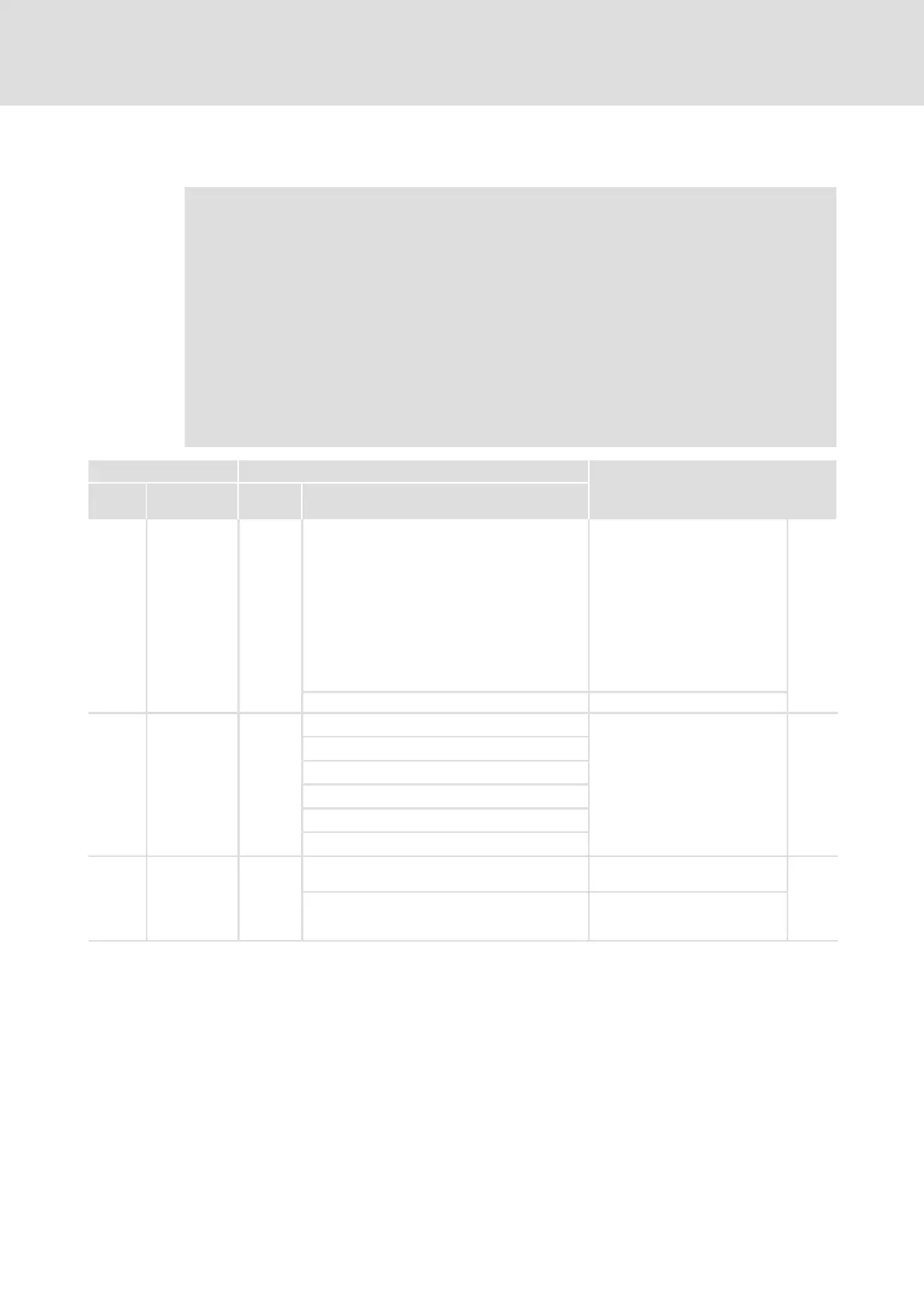
Code Possible settings IMPORTANT
No. Designation Lenze/
{Appl.}
Selection
C0350 CAN address 32 Node address for CAN bus
interface X4
l This code is not active if one
of the switches 2 ... 7 of the
DIP switch is set to "ON".
( 156)
l After the setting process, a
reset node is required.
l A definite node address must
be assigned to each CAN
node.
156
458
1 {1} 63
C0351 CAN baud rate 0 Baud rate for CAN bus interface
X4
l The baud rate must be set
identically for all CAN nodes.
l This code is not active if one
of the switches 2 ... 7 of the
DIP switch is set to "ON".
l After the setting process, a
reset node is required.
156
0 500 kbps
1 250 kbits/sec
2 125 kbit/s
3 50 kbps
4 1000 kbit/s
C2450 CANa address 1
Node address for CAN bus
interface X14 (CAN−AUX)
156
458
1 {1} 63 This code is inactive if one of DIP
switches 2 ... 7 and switch 1 are
set to "ON".

Table of Contents

Other manuals for Lenze ECS series

Questions and Answers:

Lenze ECS series Specifications

General IconGeneral
CategoryControl Unit
Protection classIP20
Product seriesECS series
Output currentDepends on specific model
Communication interfacesCANopen, Ethernet
Relative humidity5% to 95% (non-condensing)

Summary

Preface and General Information

About these Operating Instructions

Provides essential information for connecting and commissioning ECSxA axis modules, including safety instructions.

Features of the ECSxA Axis Module

Lists key features of the ECSxA axis module, including safety functions, CAN interfaces, and feedback systems.

System Block Introduction

Introduces the concept of system blocks (SB) as hardware function blocks integrated into the axis module.

Safety Instructions

General Safety and Application Notes

Covers essential safety measures for personal safety and preventing damage to material assets.

Technical Data

Rated Data

Presents technical specifications including output power, DC-bus voltage, and current ratings for axis modules.

Current Characteristics

Explains how continuous current depends on output voltage and control factor.

Mechanical Installation

Mounting with Fixing Rails (Standard Installation)

Details dimensions and mounting steps for standard installation using fixing rails.

Mounting with Thermal Separation (Push-Through Technique)

Explains mounting requirements for push-through design, including cooling and protection class.

Mounting in Cold-Plate Design

Covers requirements for collective coolers and mounting steps for cold-plate design.

Electrical Installation

Installation According to EMC

Covers electromagnetic compatibility aspects like assembly, filtering, shielding, and earthing.

Power Terminals

Details plug connectors, their assignments, and cable cross-sections for power connections.

Control Terminals

Explains connections for control electronics, digital/analog signals, and safety functions.

Commissioning

Before You Start

Lists prerequisites and checks before initial switch-on, including wiring verification.

Carrying Out Basic Settings with GDC

Details basic settings configuration using the Global Drive Control program, including motor data and feedback.

Setting of the Feedback System

Explains configuration for resolvers, TTL encoders, SinCos encoders, and absolute value encoders.

System Bus (CAN / CAN-AUX) Configuration

Setting the CAN Node Address and Baud Rate

Details setting node addresses and baud rates via DIP switches or codes for CAN interfaces.

Monitoring Functions

Fault Responses

Details the consequences and display options for TRIP, Message, Warning, FAIL-QSP, and Off responses.

Overview of Monitoring Functions

Provides a comprehensive overview of all monitoring functions, their sources, and possible responses.

Configuring Monitoring Functions

Covers setting monitoring times for process data input objects, communication errors, and bus states.

Diagnostics

Diagnostics with Global Drive Control (GDC)

Locating diagnostic codes and fault history values within the GDC parameter menu.

Troubleshooting and Fault Elimination

Fault Analysis

Methods for analyzing faults using LED displays, keypads, history buffer, and LECOM status words.

Malfunction of the Drive

Lists common drive malfunctions, their causes, and suggested remedies.

Fault Messages

Provides an overview of fault messages, their sources, and possible responses.

System Modules

DCTRL_DriveControl (Node Number 121)

Controls axis module states like Quick stop, Operation inhibit, Controller inhibit, and TRIP.

MCTRL_MotorControl (Node Number 131)

Controls driving machine functions including phase, speed, and motor control.

Appendix

Code Table

Comprehensive list of Lenze codes, their settings, and important information.

Related product manuals