AIF interface (X1) configuration
Identifiers of the process data objects
Individual identifier assignment
9
186
EDBCSXA064 EN 3.2
9.4.1 Individual identifier assignment
In case of larger system bus networks with many nodes it may be sensible to set individual
identifiers for the process data objects XCAN1_IO ... XCAN3_IO via C2353/C2354 which
are independent of the node address set in C2350:
1. Set C2353/x to "1".
– (x = Subcode of the corresponding process data object):
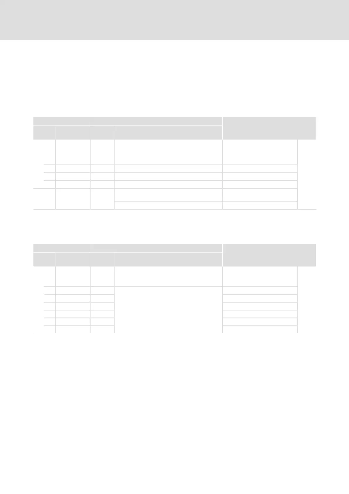
Code Possible settings IMPORTANT
No. Designation Lenze/ap
pl.
Selection
C2353 Source for system bus node
addresses of
XCAN_IN/XCAN_OUT
(AIF interface X1)
185
1 XCAN addr sel 0 CAN node address (C2350) XCAN1_IN/OUTaddress
2 XCAN addr sel 0 CAN node address (C2350) XCAN2_IN/OUTaddress
3 XCAN addr sel 0 CAN node address (C2350) XCAN3_IN/OUTaddress
0 C2350 (auto) Automatically determined by
C2350
1 C2354 (man.) Determined by C2354
2. Set in C2354/x the value which results in the desired identifier when added to
"384".
– (x = Subcode of the corresponding process data object):
Code Possible settings IMPORTANT
No. Designation Lenze/ap
pl.
Selection
C2354 Alternative node addresses for
XCAN_IN/XCAN_OUT
(AIF interface X1)
185
1 XCAN addr. 129 1 {1} 512 XCAN1_INaddress 2
2 XCAN addr. 1 XCAN1_OUTaddress 2
3 XCAN addr. 257 XCAN2_INaddress 2
4 XCAN addr. 258 XCAN2_OUTaddress 2
5 XCAN addr. 385 XCAN3_INaddress 2
6 XCAN addr. 386 XCAN3_OUTaddress 2
ƒ Ensure that the identifier of the telegram to be sent must correspond to the
identifier of the process data object to be addressed.
ƒ In case the addresses are assigned individually, the identifier for the process data
objects is made up as follows:
Identifier = 384 + value of C0354/x
ƒ Thus, identifiers can be assigned for the process data objects within the range
385 ... 896.