System bus (CAN / CAN−AUX) configuration
Axis synchronisation (CAN synchronisation)
8
166
EDBCSXA064 EN 3.2
8.6 Axis synchronisation (CAN synchronisation)
By means of the axis synchronisation, the internal time base can be synchronised with the
instant of reception of the sync signal. By this, the start of cyclic internal processes of all
drives involved in the synchronisation is synchronous.
Sync signal source
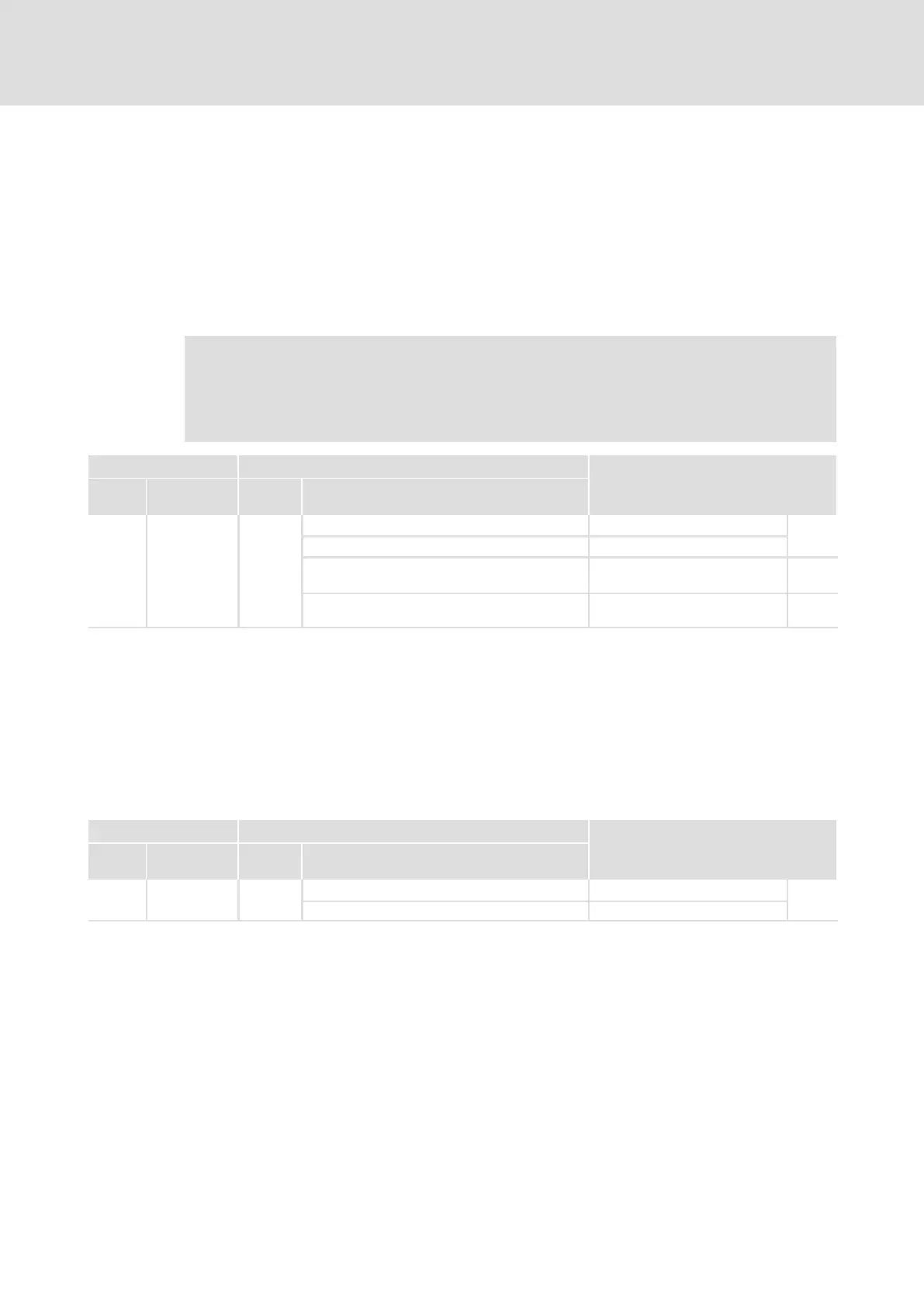
The sync signal source is set via C1120:
Note!
If synchronisation takes place via X6/DI1 terminal, the control configuration of
the "Drive PLC Developer Studio" (DDS) must not only comprise the
SB CAN_Synchronization ( 281) but also the SB DIGITAL_IO. ( 343)
Code Possible settings IMPORTANT
No. Designation Lenze/
{Appl.}
Selection
C1120 Sync mode 0
Sync signal source
166
0 Off Off
1 CAN sync Sync connection via interface X4
(CAN)
170
2 Terminal sync Sync connection via terminal
X6/DI1
171
Synchronisation cycle
For the purpose of synchronisation the master sends a cyclic CAN sync telegram.
The controllers receive the CAN sync telegram and control the starting time of their own
program cycle in relation to the instant of reception of the CAN sync signal. The start is to
be offset by the synchronisation phase (C1122).
The synchronisation cycle set under C1121 must be set the same as the transmission cycle
of the CAN sync telegrams.
Code Possible settings IMPORTANT
No. Designation Lenze/
{Appl.}
Selection
C1121 Sync cycle 2
Synchronisation cycle
166
1 {1 ms} 13

 Loading...


