Troubleshooting and fault elimination
Fault analysis
Fault analysis via the LED display
12
236
EDBCSXA064 EN 3.2
12 Troubleshooting and fault elimination
Failures can be quickly detected by means of display elements or status messages via the
system bus (CAN/CAN−AUX).
Display elements and status messages provide a rough classification of the trouble.
In the chapter "12.3.2 Causes and remedies" ( 246) , you can find information on fault
elimination.
12.1 Fault analysis
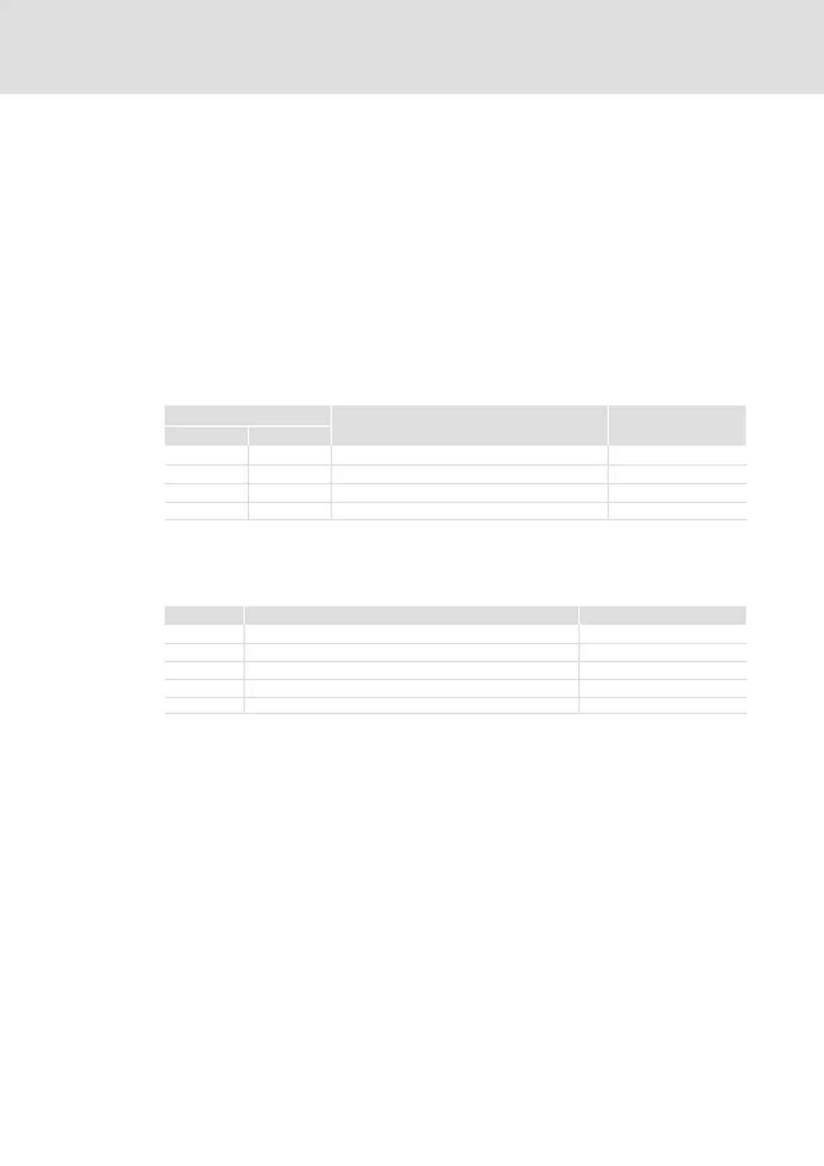
12.1.1 Fault analysis via the LED display
LED
Operating state Check
Red Green
Off On Controller enabled, no fault
Off Blinking Controller inhibit (CINH) active, switch−on inhibit C0183
Blinking Off Trouble/fault (TRIP) is active C0168/1
Blinking On Warning/FAIL−QSP is active C0168/1
12.1.2 Fault analysis with keypad XT EMZ9371BC
The status messages in the display indicate the controller status.
Display Controller status Check
RDY Controller ready for operation, controller can be inhibited. C0183, C0168/1
IMP Pulses at the power stage inhibited. C0183, C0168/1
Imax Maximum current reached.
Mmax Maximum torque reached.
FAIL Fault through TRIP, message, fail QSP or warning. C0183, C0168/1

 Loading...


