
Do you have a question about the Lenze ECS series and is the answer not in the manual?
| Category | Control Unit |
|---|---|
| Protection class | IP20 |
| Product series | ECS series |
| Output current | Depends on specific model |
| Communication interfaces | CANopen, Ethernet |
| Relative humidity | 5% to 95% (non-condensing) |
Provides essential information for connecting and commissioning ECSxA axis modules, including safety instructions.
Lists key features of the ECSxA axis module, including safety functions, CAN interfaces, and feedback systems.
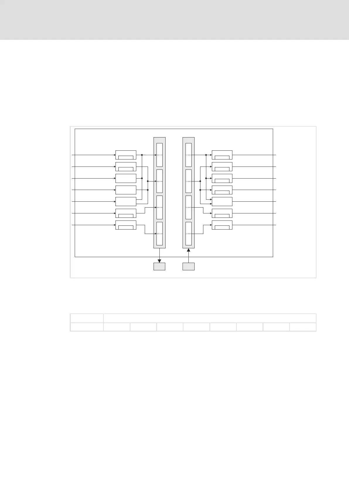
Introduces the concept of system blocks (SB) as hardware function blocks integrated into the axis module.
Covers essential safety measures for personal safety and preventing damage to material assets.
Presents technical specifications including output power, DC-bus voltage, and current ratings for axis modules.
Explains how continuous current depends on output voltage and control factor.
Details dimensions and mounting steps for standard installation using fixing rails.
Explains mounting requirements for push-through design, including cooling and protection class.
Covers requirements for collective coolers and mounting steps for cold-plate design.
Covers electromagnetic compatibility aspects like assembly, filtering, shielding, and earthing.
Details plug connectors, their assignments, and cable cross-sections for power connections.
Explains connections for control electronics, digital/analog signals, and safety functions.
Lists prerequisites and checks before initial switch-on, including wiring verification.
Details basic settings configuration using the Global Drive Control program, including motor data and feedback.
Explains configuration for resolvers, TTL encoders, SinCos encoders, and absolute value encoders.
Details setting node addresses and baud rates via DIP switches or codes for CAN interfaces.
Details the consequences and display options for TRIP, Message, Warning, FAIL-QSP, and Off responses.
Provides a comprehensive overview of all monitoring functions, their sources, and possible responses.
Covers setting monitoring times for process data input objects, communication errors, and bus states.
Locating diagnostic codes and fault history values within the GDC parameter menu.
Methods for analyzing faults using LED displays, keypads, history buffer, and LECOM status words.
Lists common drive malfunctions, their causes, and suggested remedies.
Provides an overview of fault messages, their sources, and possible responses.
Controls axis module states like Quick stop, Operation inhibit, Controller inhibit, and TRIP.
Controls driving machine functions including phase, speed, and motor control.
Comprehensive list of Lenze codes, their settings, and important information.


