Preface and general information
System block introduction
Signal types and scaling
1
27
EDBCSXA064 EN 3.2
1.5.7 Signal types and scaling
A signal type can be assigned to most inputs and outputs of the Lenze function
blocks/system blocks. The following signal types are distinguished:
ƒ digital and analog signals
ƒ position and speed signals
The identifier of the corresponding input/output variable has an ending (starting with an
underscore). It indicates the signal type.
Signal
Ending Memory
Scaling
(external size º internal size)
Type Symbol
Analog _a (analog) 16 Bit1 100 % º 16384
Digital _b (binary) 1 bit 0 º FALSE; 1 º TRUE
Angular
difference or
speed (rot.)
_v (velocity) 16 Bit1 15000 rpm º 16384
l Angular difference/speed ref. to 1 ms
l Normalisation example:
1 motor revolution + 65536 [inc]
Variable value (..._v) +
15000
60000 [ms]
@ 65536 [inc] + 16384
ƪ
inc
ms
ƫ
Speed (on motor side) + 15000 [rpm] +
15000
60 [s]
Angle or position
_p (position) 32 Bit 1 motor revolution º 65536
High Word Low Word 031
Direction (0 º clockwise rotation; 1 º counter−clockwise rotation)
No. of motor revolutions (0 ... 32767)
Angle or position (0 ... 65535)
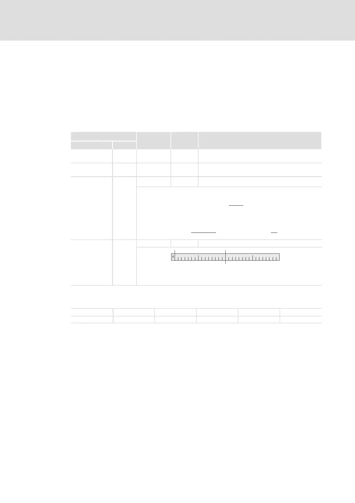
Due to their scaling, analog signals have an asymmetrical resolution range
(−200 % ... +199.99 %):
External: −200 % −100 % 0 % +100 % +199.99 %
Internal: −32768 −16384 0 +16384 +32767

 Loading...


