Preface and general information
System block introduction
Node numbers
1
22
EDBCSXA064 EN 3.2
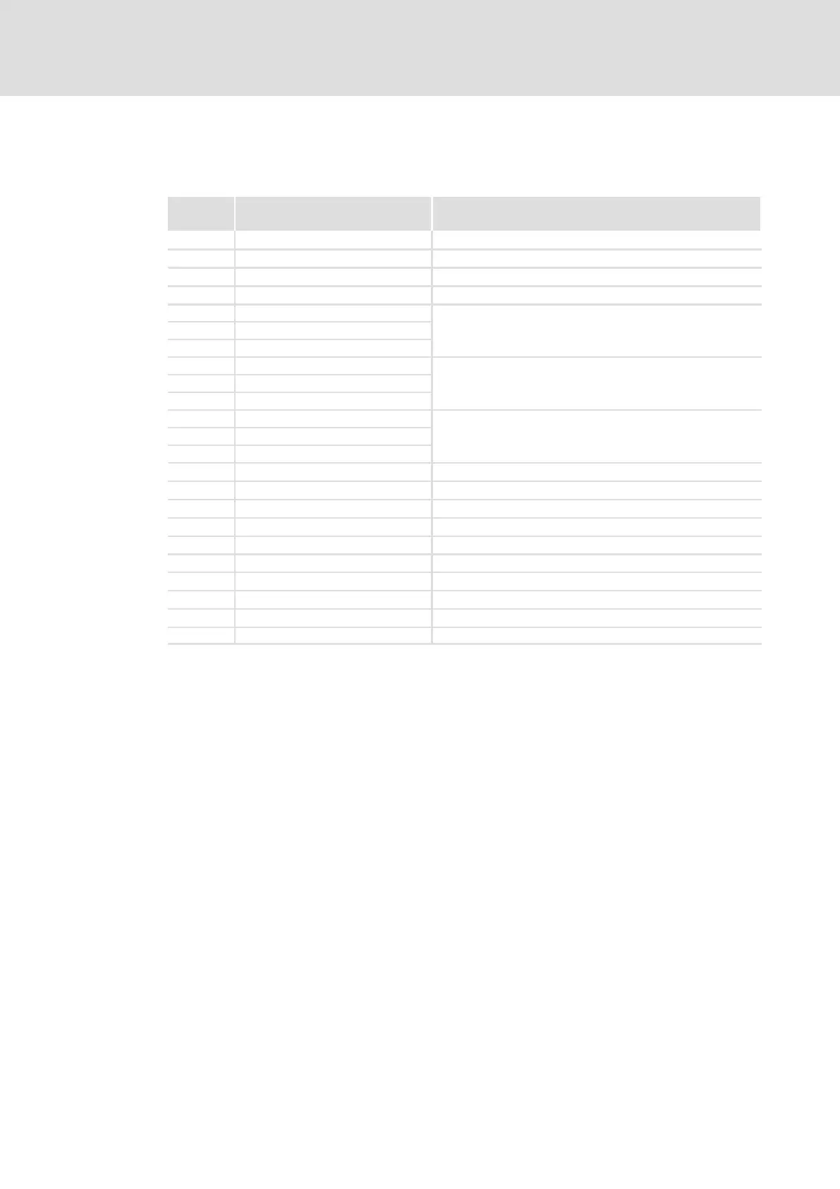
1.5.2 Node numbers
The system blocks feature the following node numbers:
Node
number
System block Notes
1 DIGITAL_IO Digital inputs/outputs
11 ANALOG1_IO Analog input 1
21 DFIN_IO_DigitalFrequency Digital frequency input
22 DFOUT_IO_DigitalFrequency Digital frequency output
31 CAN1_IO
System bus (CAN)
32 CAN2_IO
33 CAN3_IO
34 CANaux1_IO
System bus (CAN−AUX)
35 CANaux2_IO
36 CANaux3_IO
41 AIF1_IO_AutomationInterface
Automation interface (AIF)
42 AIF2_IO_AutomationInterface
43 AIF3_IO_AutomationInterface
60 OSC_Oscilloscope Oscilloscope function
101 CAN_Management System bus (CAN) management
102 CAN_Synchronization System bus (CAN) synchronisation
111 CANaux_Management System bus (CAN−AUX) management
121 DCTRL_DriveControl Device control
131 MCTRL_MotorControl Motor control
141 FCODE_FreeCodes Free codes
151 SYSTEM_FLAGS System flags
161 AIF_IO_Management Automation interface management
171 VAR_PERSISTENT Persistent variables
The node number is part of the absolute system bus address ( 24).

 Loading...


