Electrical installation
Power terminals
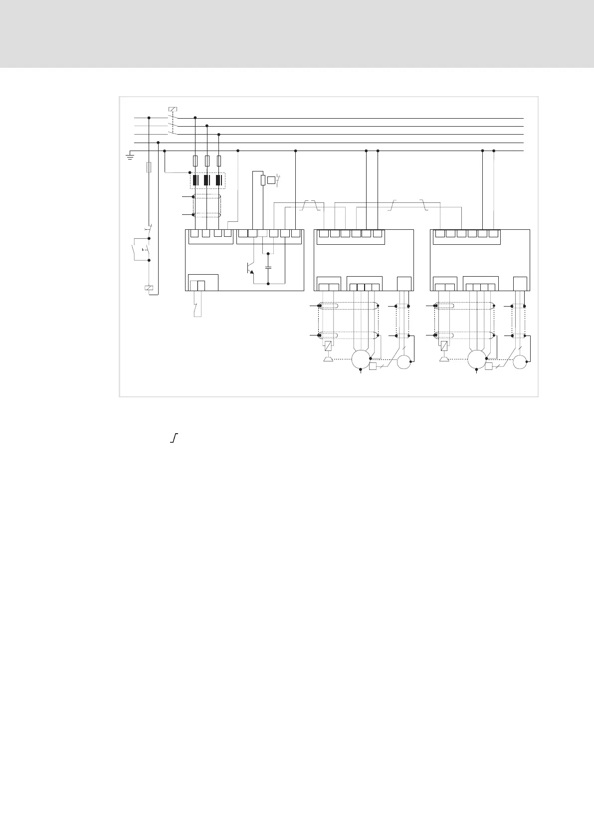
Connection plan for mimimum wiring with external brake resistor
5
69
EDBCSXA064 EN 3.2
F4
K1
K1
Off
On
L3
N
L1
L2
K1
F1...F3
Z1
L1 L2
L3
PE
X21
+UG
+UG
+UG
-UG
-UG
-UG
PE
PE
PE
X22
X23
+UG
BR1
BR0
M
3~
R
T1
T2
X6
...
J
2
6
0
UV
W
PE
X24
BD1
BD2
X25
X7
"
"
+
"
"
+UG
+UG
-UG
-UG
PE
PE
X23
M
3~
R
J
2
6
0
UV
W
PE
X24
BD1
BD2
X25
X7
+
"
"
"
"
ECSxS/P/M/A...
ECSxE...
ECSxS/P/M/A...
J
J
Rb
ext
"
"
(Rb
ext
)
ECSXA012
Fig. 5−3 Interconnected power system with external brake resistor
HF−shield termination by large surface connection to functional earth (see mounting
instructions for shield mounting ECSZS000X0B)
Twisted cables
K1 Mains contactor
F1 ... F4 Fuse
Z1 Mains choke / mains filter, optional
Rb
ext
External brake resistor
J KTY thermal sensor of the motor
System cable for feedback

 Loading...


