Electrical installation
Power terminals
Motor holding brake connection
5
72
EDBCSXA064 EN 3.2
5.2.5.3 Requirements on the brake cables
ƒ Use a Lenze system cable with integrated brake cable.
– The shielding of the brake cable must be separated.
ƒ Length: max. 50 m
ƒ If a separately installed brake cable is required, lay it in a shielded manner.
Note!
Due to the monitoring circuit of the brake connection, an additional constant
voltage drop of 1.5 V is produced. The voltage drop can be compensated by a
higher voltage at the cable entry.
The voltage required at X6/B+ and X6/B− for the Lenze system cables is calculated as
follows:
U
K
[V] + U
B
[V] ) 0.08
ƪ
V
m @ A
ƫ
@ L
L
[m] @ I
B
[A] ) 1.5[V]
V
comp
Voltage required at 6X/B+ and X6/B− [V]
V
B
Rated operating voltage of the brake [V]
L
L
Length of the brake cable [m]
I
B
Brake current [A]
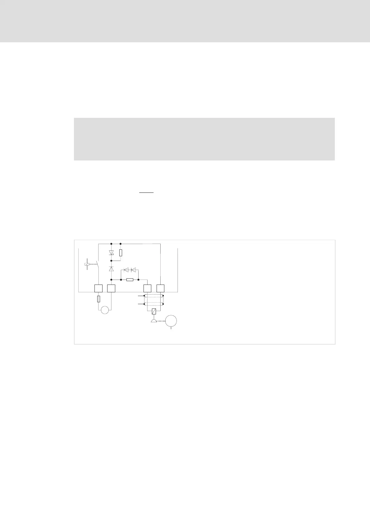
B+
B-
X6
BD2
BD1
X25
+
+23 ... +30 V DC
max. 1.5 A
F 1.6 A
_
+
_
1.5 A
M
3~
+
"
"
ECSXA017
Fig. 5−5 Connection of the motor holding brake to X25
HF−shield termination by large−surface connection to functional earth (see Mounting
Instructions for ECSZS000X0B shield mounting kit)

 Loading...


