Configuration Examples
366
ProSAFE 10-Gigabit Smart Managed Switch XS728T and XS748T User Manual
MSTP Example Configuration
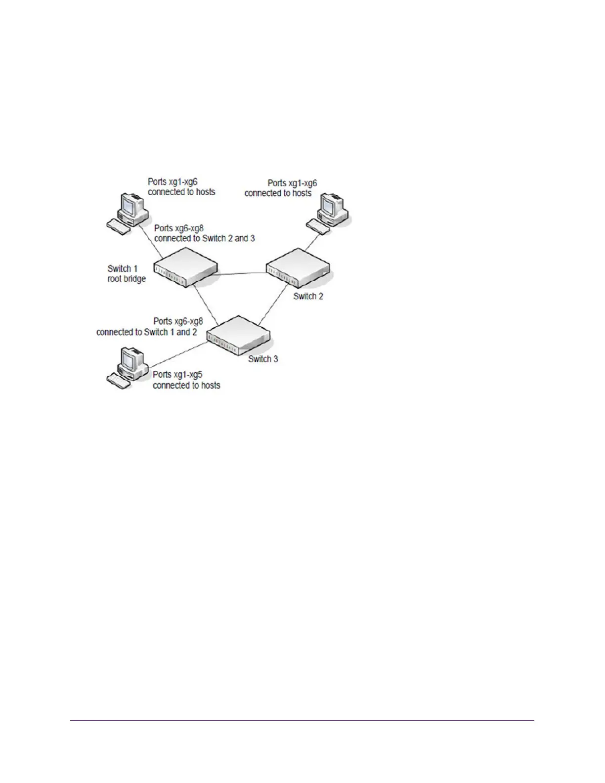
This example shows how to create an MSTP instance from the switch. The example network
includes three different switches that serve different locations in the network. In this example,
ports xg1–xg5 are connected to host stations, so those links are not subject to network loops.
Ports xg6–xg8 are connected across switches 1, 2, and 3.
Figure 2. MSTP sample configuration
Perform the following procedures on each switch to configure MSTP:
1. On the VLAN Configuration page, create VLANs 300 and 500 (see Configure VLAN
Settings on page 94).
2. On the VLAN Membership page, include ports xg1–xg8 as tagged (T) or untagged (U)
members of VLAN 300 and VLAN 500 (see Configure VLAN Membership on page 97).
3. On the STP Configuration page, enable the Spanning Tree State option (see Configure STP
Settings on page 118).
Use the default values for the rest of the STP configuration settings. By default, the STP
operation mode is MSTP and the configuration name is the switch MAC address.
4. On the CST Configuration page, set the bridge priority value for each of the three switches
to force Switch 1 to be the root bridge:
• Switch 1. 4096
• Switch 2. 12288
• Switch 3. 20480
Note: Bridge priority values are multiples of 4096.
 Loading...