5
SAFETY I/O interface
5-1
1. SAFETY I/O interface overview
A SAFETY I/O interface is prepared to construct a robot safety circuit. Use the terminals to construct a safety
circuit so that the system including the controller operates toward the safe side. Additionally, connect the I/O
terminals correctly and effectively, and then start the operation after checking the operation of the safety circuit
sufficiently.
Connector name Connector type number Wire thickness
SAFETY
DFMC 1,5/12-ST-3,5-LR BK 2BD
Manufacturer: Phoenix Contact
AWG24-16
1.1 Power
The emergency stop input uses either the controller’s internal power for emergency stop, or external 24 V power.
Additionally, the AUTO mode input (valid only for the CE specifications) uses the external 24 V power.
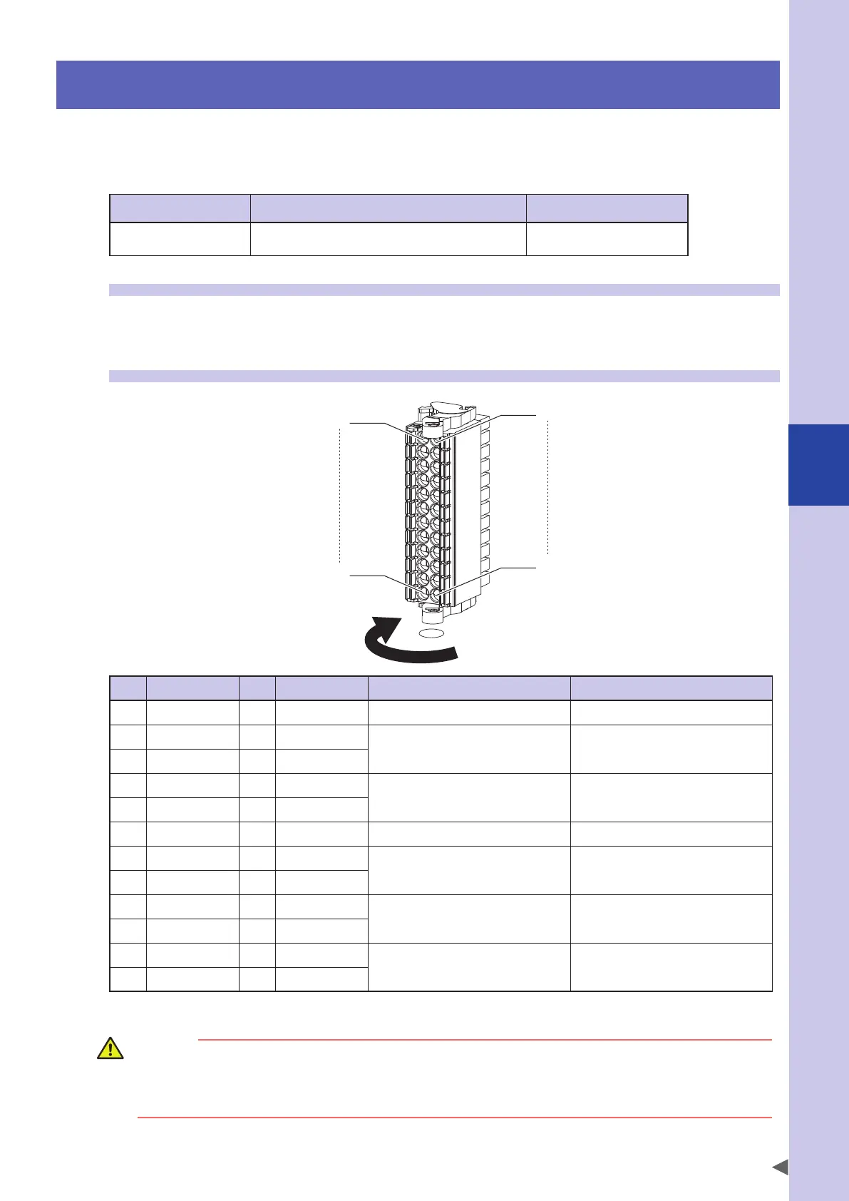
1.2 Connector I/O signals
A1
A12
B1
B12
Release
Lock
PIN I/O No. PIN I/O No. Name Remarks
B1 E-STOP2+ A1 E-STOP1+ Internal power (+) for emergency stop
B2 E-STOP21 A2 E-STOP11
Emergency stop contact output
B3 E-STOP22 A3 E-STOP12
B4 E-STOP RDY2 A4 E-STOP RDY1
Emergency stop ready input +24 V/45 mA
B5 E-STOP COM2 A5 E-STOP COM1
B6 E-STOP2- A6 E-STOP1- Internal power (-) for emergency stop
B7 ENABLE2+ A7 ENABLE1+
Enable switch contact output
1 A/30 Vmax
Valid only when PBEX is connected.
B8 ENABLE2- A8 ENABLE1-
B9 AUTO2+ A9 AUTO1+
AUTO mode input
7 mA at24 V
Valid only for the CE specifications
B10 AUTO COM2 A10 AUTO COM1
B11 MP RDY2+ A11 MP RDY1+
Motor power ready output
30 V DC/300 mAmax
(MOS FET contact)
B12 MP RDY2- A12 MP RDY1-
The I/O signals have two systems; line A and line B of the connector.
CAUTION
• Construct a physical emergency stop circuit so that the system including the controller operates toward the
safe side.
• Do not connect any external power to "E-STOP+/-" of the internal power for the emergency stop. Additionally,
do not use "E-STOP+/-" for a purpose other than the emergency stop.
For details regarding the definition of NPN and PNP specifications, refer to "7. I/O connections" in Chapter 3.
 Loading...


