EasyManua.ls Logo

Omron YRC User Manual

Omron YRC
260 pages
To Next Page IconTo Next Page
To Previous Page IconTo Previous Page
Page #144 background imageLoading...
Page #144 background image
7
Controller system settings
7-8
8. Initialize
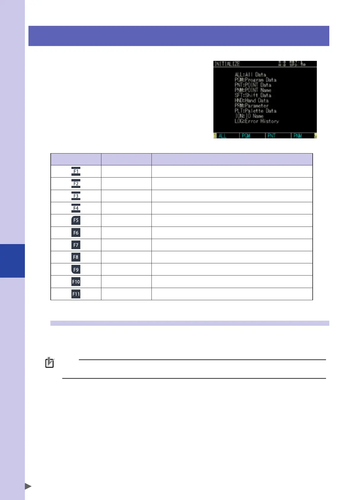
When selecting [System] - [Initialize] from the
initial screen, the "Initialize" screen will appear.
On this screen, you can initialize the data managed
by the controller. Use the F1 key (ALL DATA) to F11
(CLOCK) to select the item to initialize.
"INITIALIZE" screen
Valid keys and submenu descriptions on the "INITIALIZE" screen are shown below.
Valid keys Menu Function
ALL Initializes all data.
PGM Deletes the program data.
PNT Deletes the point data.
PNM Deletes the point name data.
SFT Deletes the shift coordinate data.
HND Deletes the hand definition data.
PRM Initializes the parameter data.
PLT Deletes the pallet definition data.
ION Deletes the I/O name data.
LOG Deletes the alarm history data.
CLOCK Sets the clock.
8.1 Initializing the data
Programs, point data, point names, shift coordinates, hand definitions, parameters, pallet definitions, IO
names, and alarm history data are initialized or deleted.
Before executing the initialization process, carefully check that the currently input data is unnecessary.
NOTE
Once the memory is initialized, the external data needs to be input to restore the data.
If the memory is corrupted for some reason, the memory needs to be initialized.

Table of Contents

Question and Answer IconNeed help?

Do you have a question about the Omron YRC and is the answer not in the manual?

Omron YRC Specifications

General IconGeneral
SeriesYRC
Programming LanguageINFORM
Protection ClassIP20
Communication ProtocolsEtherNet/IP
Safety StandardsISO 10218-1
Power Supply200-230V AC, 50/60Hz
Operating Temperature0°C to 45°C
Programming MethodTeach pendant or offline programming
I/O InterfaceDigital I/O, analog I/O, fieldbus options
Humidity20% to 80% (non-condensing)

Summary

Safety Information

Warning labels

4. Important precautions for each stage of the robot life cycle

4.1 Precautions for using robots and controllers

General precautions, including applications where robots cannot be used and operator qualifications.

4.2 Design

4.3 Moving and installation

4.3.2 Precautions for robot controllers

4.4 Safety measures

4.4.1 Safety measures

General safety measures, referring to labels, drawing up work instructions, and taking safety measures.

4.4.2 Installing a safety enclosure

4.5 Operation

4. Working inside safety enclosures

4.5.2 Automatic operation

4.6 Inspection and maintenance

4.6.2 Precautions during service work

5. Emergency action when a person is caught by robot

7. Using the robot safely

7.2 Robot protective functions

7.4 Special training for industrial robot operation

Before using the robot controller (Be sure to read the following notes)

Chapter 1 Using the robot safely

1. Emergency action when a person is caught by robot

Steps to take if a person is caught by the robot, including axis release procedures.

2. Emergency stop

How to perform an emergency stop using the button on the programming box.

3. Power-ON procedures

Step-by-step guide for powering on the controller and performing return-to-origin.

1. Emergency action when a person is caught by robot

2. Emergency stop

2.1 Emergency stop release and alarm reset

Steps to release emergency stop and reset alarms after an event.

3. Power-ON procedures

4. Usage environments

Chapter 2 System overview

4. Basic sequence from installation to operation

Outlines the sequence of steps from initial installation to robot operation.

4. Basic sequence from installation to operation

Chapter 3 Installation

2. Installing the robot controller

Steps and conditions for installing the robot controller.

3. Connecting to the power

Instructions for connecting the controller to the power supply.

5. Robot connections

Instructions for connecting robot cables to the controller.

11. Checking the robot controller operation

Steps to check the controller operation after connections.

Chapter 4 I/O interface

1.9 Dedicated input signal description

1.10 Dedicated output signal description

1.11.2 Controller emergency stop and servo on reset

1.11.3 Return-to-origin

1.11.4 Program reset and program execution

1.11.5 Stopping by program stop

Chapter 5 SAFETY I/O interface

1. SAFETY I/O interface overview

Introduction to the SAFETY I/O interface for constructing robot safety circuits.

1.3 Connection example combining the programming box with external emergency stop circuit

Example of connecting the programming box with an external emergency stop circuit.

1.3.1 Connection example of controller with CE specifications and PBEX

1.4 Connections example of dedicated input signal

1.4.1 Emergency stop inputs (E-STOP RDY*, E-STOP COM*)

Wiring examples for emergency stop input signals.

1.5 Connection example of dedicated output signal

1.5.1 Emergency stop contact outputs (E-STOP*1, E-STOP*2)

Wiring examples for emergency stop contact outputs.

1.5.3 Motor power ready outputs (MP RDY*+, MP RDY*-)

Chapter 6 External communication interface

2. RS-232C

2.4 Communication parameter setting

3. Ethernet

3.4 Parameter setting on controller (server)

3.4.1 Setting the communication mode and parameters

3.5 System setting on personal computer (client)

3.6 Connection check using "Ping"

3.7 Communication example using "TELNET.EXE"

4. General Ethernet port (GEP)

4.2 GEP parameter setting method

Chapter 7 Controller system settings

7. Safety setting

Setting safety parameters to ensure safe robot operation.

8. Initialize

Procedures for initializing controller data.

10. Parameters

Overview of available parameters for controller, robot, axis, etc.

5. USB memory operation

5.2 Loading the data

6. Execution level

7. Safety setting

8. Initialize

8.1 Initializing the data

Details on initializing various controller data types.

10. Parameters

10.2 Setting the parameters

Guide to setting controller and robot operation parameters.

Controller parameters

Robot parameters

Axis parameters

I/O parameters

Chapter 8 Periodic inspection

3. Periodic inspections

Details daily and periodic inspection procedures.

4. Replacing the absolute battery

Procedure for replacing the absolute battery when it's low.

5. Replacing the memory battery

Procedure for replacing the memory battery and associated data backup precautions.

3.1 Daily inspections

4. Replacing the absolute battery

5. Replacing the memory battery

Chapter 9 Specifications

1. Controller

General specifications for the robot controller.

1. Controller

1.1 Specifications

Detailed technical specifications including connected motor capacity, dimensions, and axis control.

1.2 Basic functions

2. Programming box

Troubleshooting

1. Alarm messages

Details alarm messages related to the controller and programming box.

1.1 Alarm messages related to the controller

Categorizes controller alarms by group and classification numbers.

1.1.1 Alarm group number list

Lists alarm messages classified into groups [0] to [30] based on contents.

1.1.2 Alarm classification number list

Details alarm codes, types, error operations, history, LED display, and reset methods.

1.1.3 Warning number list

Categorizes warning messages by type, axis operation, history, and reset methods.

2. Troubleshooting

Provides guidance on troubleshooting when problems occur.

1.1 Alarm messages related to the controller

Checking the alarm occurrence status

How to check the current alarm status via programming box or external communication.

1.1.1 Alarm group number list

1.1.2 Alarm classification number list

1.1.3 Warning number list

2. Troubleshooting

2.1 When trouble occurs

Information to provide to a distributor when reporting a problem.

2.2.1 Checking the alarm occurrence status

2.2.2 Checking the alarm history

2.3 Troubleshooting checkpoints

2.3.1 Installation and power supply

Checkpoints and corrective actions for installation and power supply issues.

2.3.2 Robot operation

Checkpoints and corrective actions for robot operation issues like abnormal sound or position deviation.

2.3.3 I/O

Related product manuals