5
SAFETY I/O interface
5-3
1.4 Connections example of dedicated input signal
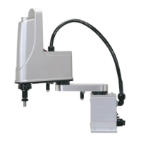
1.4.1 Emergency stop inputs (E-STOP RDY*, E-STOP COM*)
E-STOP RDY1
3.3kΩ
7 mA
DC24V
E-STOP COM1
E-STOP RDY2
3.3kΩ
7 mA
E-STOP COM1
L
N
45 mA
45 mA
To main power circuit
Main power on/off control
The emergency stop inputs are used to construct a physical emergency stop circuit as a safety protection
function of the overall system including the controller.
To operate the robot, the emergency stop input contact needs to be closed.
When the emergency stop input contact is closed (ON), the servo power can be turned on. When any
emergency stop input contact is open (OFF), the servo power cannot be turned on.
To drive the internal power relay that is connected in parallel, E-STOP RDY*/E-STOP COM* needs 45-mA
current.
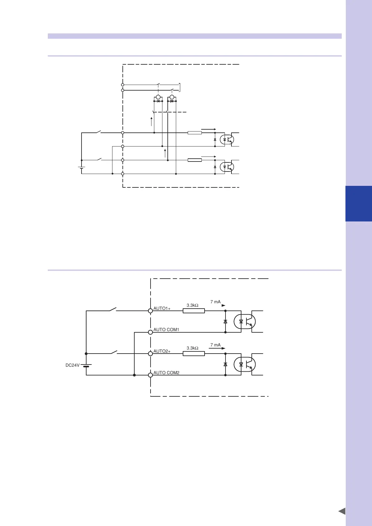
1.4.2 AUTO mode inputs (AUTO*+, AUTO COM*)
The AUTO mode inputs are valid only for the controller with the CE specifications.
They can change the external safety circuit of the controller to the AUTO mode and inform that the robot is in
the automatic operation ready status. When either AUTO mode input turns off, the controller changes to the
MANUAL mode. For the controller with the standard specifications, the operation mode can be changed only
from the manual lock switch on the programming box.
 Loading...


