6
External communication interface
6-4
2. RS-232C
2.1 Connectors and cables
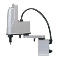
The RS-232C interface connector is located on the front panel of the robot controller as shown below.
RS-232C interface
Pin No.
9
8
7
6
Pin No.
5
4
3
2
1
YRCX
NOTE
The controller connector is a 9-pin D-Sub female type. Use male type for the connection cable.
■
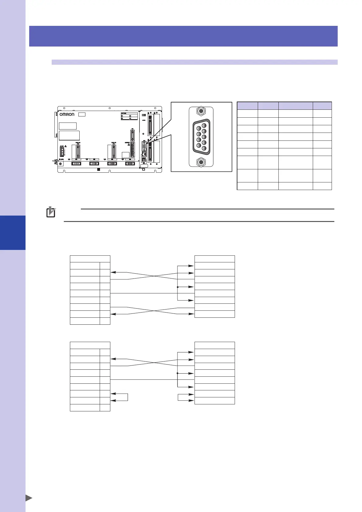
Cable wiring for connections
a. Cable of hardware busy control
NC
RXD
TXD
NC
GND
NC
RTS
CTS
NC
1
2
3
4
5
6
7
8
9
Controller
DCD
RXD
TXD
DTR
GND
DSR
RTS
CTS
External device
b. Cable without using control wires
NC
RXD
TXD
NC
GND
NC
RTS
CTS
NC
1
2
3
4
5
6
7
8
9
Controller
DCD
RXD
TXD
DTR
GND
DSR
RTS
CTS
External device
* When arranging signal wiring on an external device, be sure to refer to the manufacturers manual.
Pin No.
Name Description
I/O
1 NC Not used
2 RXD Receive data Input
3 TXD Send data Output
4 NC Not used
5 GND GND
6 NC Not used
7 RTS
Request to
send
Output
8 CTS
Permission
to send
Input
9 NC Not used
 Loading...


