3
Installation
3-15
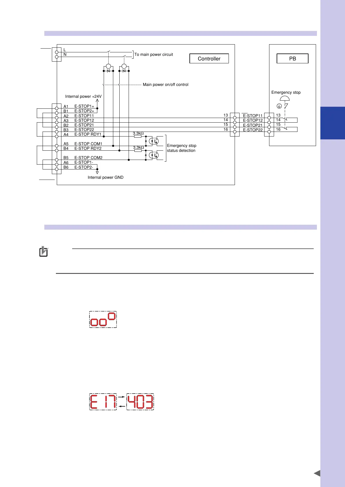
11.2 Wiring example of emergency stop circuit for operation check
PB
Main power on/off control
Emergency stop
status detection
SAFETY
ACIN
The emergency stop button contacts of the programming box are output from the A2, A3, B2, and B3 pins of
the SAFETY connector through the PB connector.
11.3 Operation check
Supply the power to the controller after connecting the controller, robot, and supplied connector.
NOTE
When the option boards are installed without wiring, it goes in abnormal status, such as error occurring and
emergency stop. To check the operation, set the option boards “Valid" temporarily. Refer to "10.8 Option board
related parameters" in Chapter 7 for details.
Normal status
· The "PWR" LED on the front of the controller is lit and the 7-segment LED displays as follows.
(Servo off, return-to-origin incomplete, emergency stop released)
Abnormal status
· The "PWR" LED on the front of the controller is lit and the 7-segment LED displays the alarm code.
· Check the alarm message shown on the programming box and take corrective actions while referring to the
troubleshooting.
(Example) Display if an alarm occurs.
"E + alarm group number" and "alarm classification number" are displayed alternately.
* For details about alarm contents shown by each alarm code, refer to "Troubleshooting".
 Loading...


