4
I/O interface
4-1
1. I/O interface overview
To make the robot applicable to the customer's system, the dedicated or general-purpose I/O interface can
be selected for the controller. Add an optional parallel I/O board to the controller to use the I/O interface.
The parallel I/O board can select the standard specifications that include the dedicated I/O or the expanded
specifications that have only the general-purpose I/O. Up to four boards can be installed.
The standard/expanded specifications and the PNP/NPN specifications of the parallel I/O board are
determined at shipment.
Additionally, when the serial I/O is selected, dedicated inputs other than DI06 (Stop) of the parallel I/O
board become invalid.
For details about the definitions of the NPN and PNP specifications, refer to "7. I/O connections" in
Chapter 3. In the following descriptions, the input signal and output signal are expressed as "DI" and "DO",
respectively.
NOTE
The dedicated inputs are limited to ensure the safety during manual operation of the robot.
Specifications Connector name Connector type number Wire thickness
Standard
specifications
Input
Dedicated 8
STD.DIO
Shell: 10350-52A0-008
Plug: 10150-3000PE
Manufacturer:
SUMITOMO 3M
AWG30 to 24
General-purpose 16
Output
Dedicated 9
General-purpose 8
Expanded
specifications
Input 24 (Max. 96)
EXP.DIO
Output 16 (Max. 64)
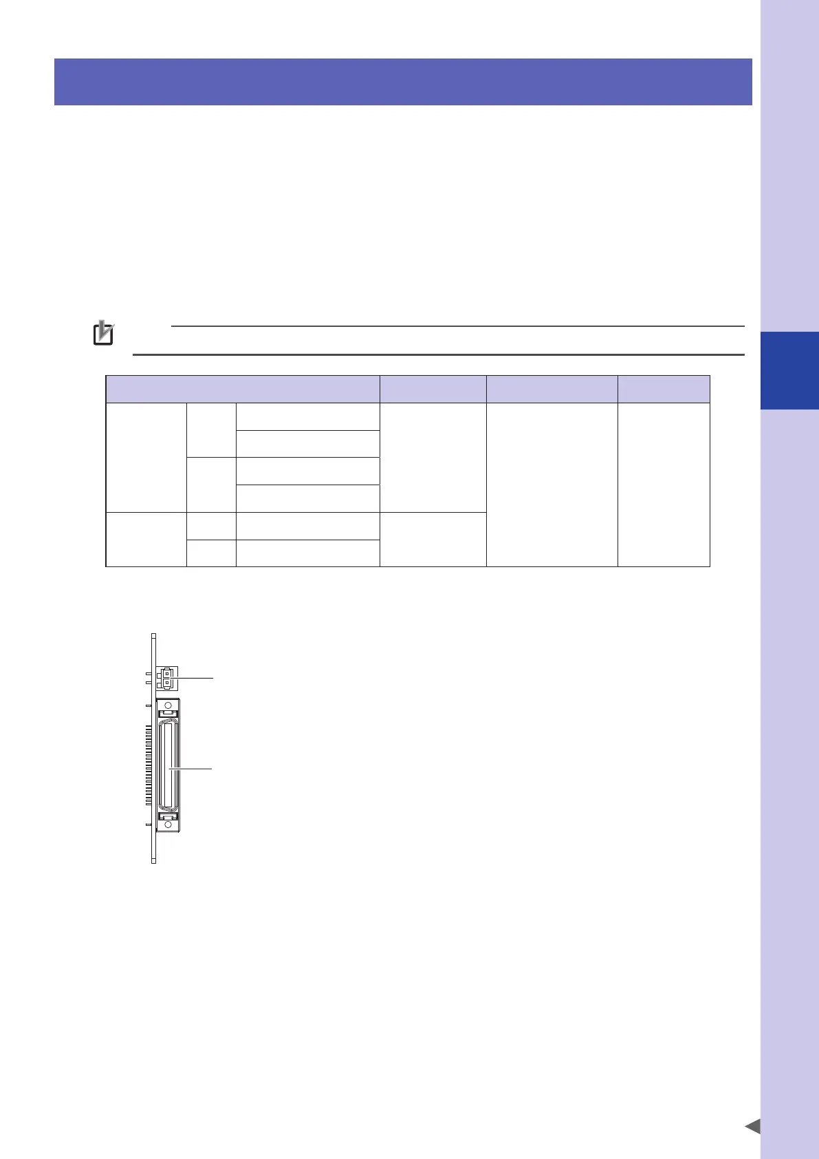
■
Parallel I/O board
Parallel I/O connector
Power connector
 Loading...


