3
Installation
3-11
7. I/O connections
The various input/output (I/O) signals from peripheral equipment can be connected to the robot controller.
Each I/O is set with a number, and the I/O connector to be used depends on that number.
For more detailed information on inputs and outputs, refer to Chapter 4, "I/O interface" or Chapter 5,
"SAFETY I/O interface". The terms used in the manual are described as follows.
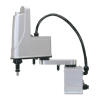
■
NPN specifications
NPN specifications indicate that a DO (digital output) type NPN open-collector transistor is used for the I/O port having
a transistor and photo-coupler, and a corresponding DI (digital input) is also used. NPN specifications therefore make use
of a sink output and a source input (see the figure below).
Current
Current
DO output (sink type)
DI input (source type)
N.COM
NPN
P.COM
■
PNP specifications
PNP specifications indicate that a DO (digital output) type PNP open-collector transistor is used for the I/O port having
a transistor and photo-coupler, and a corresponding DI (digital input) is also used. PNP specifications therefore make use
of a source output and a sink input (see the figure below).
Current
Current
DO output (source type)
DI input (sink type)
N.COM
PNP
P.COM
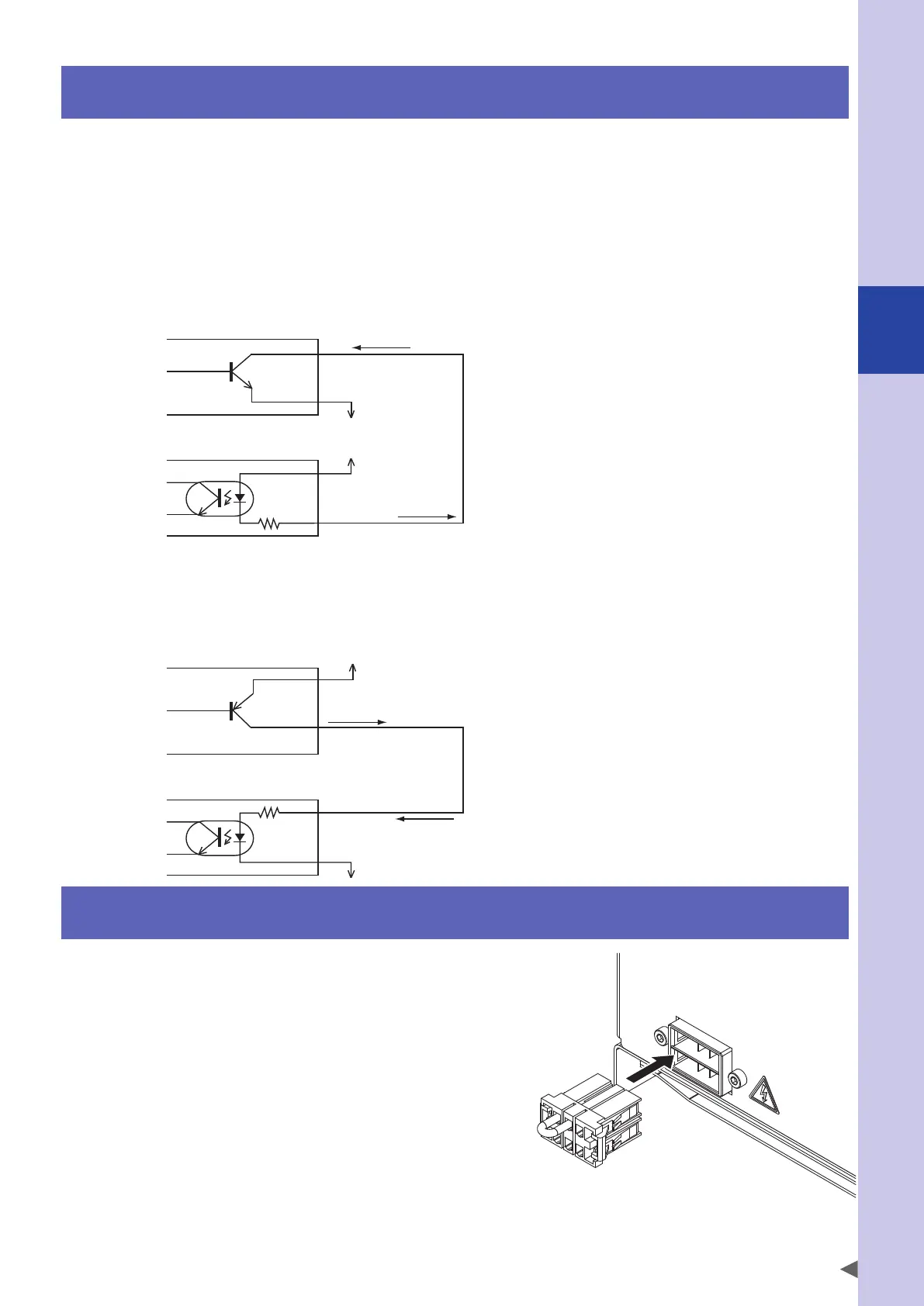
8. Connecting the regenerative shorting connector
A regenerative unit is incorporated.
To disable the temperature error monitor of expanded
regenerative unit, connect the shorting connector.
 Loading...


