5
SAFETY I/O interface
5-4
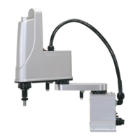
1.5 Connection example of dedicated output signal
1.5.1 Emergency stop contact outputs (E-STOP*1, E-STOP*2)
E-STOP11
E-STOP12
E-STOP21
E-STOP22
PBEX
Emergency stop
Controller
The emergency stop contact outputs are used to construct a physical emergency stop circuit as a safety
protection function of the system including the controller. To operate the robot, the contact needs to be closed.
The emergency stop switch contacts are connected to that of the programming box.
1.5.2 Enable switch contact outputs (ENABLE*1, ENABLE*2)
PBEX
Controller
ENABLE11
ENABLE12
ENABLE21
ENABLE22
Enable
The enable switch contact outputs are connected to the enable switch contacts of the programming box.
Three-position enable switch status is informed to the external system as a safety protection function of the
system including the controller.
Construct an external system so that it monitors the enable switch status (always on) in the MANUAL mode to
permit the main power supply to the controller.
 Loading...


