Parker Hannifin
Topic Description
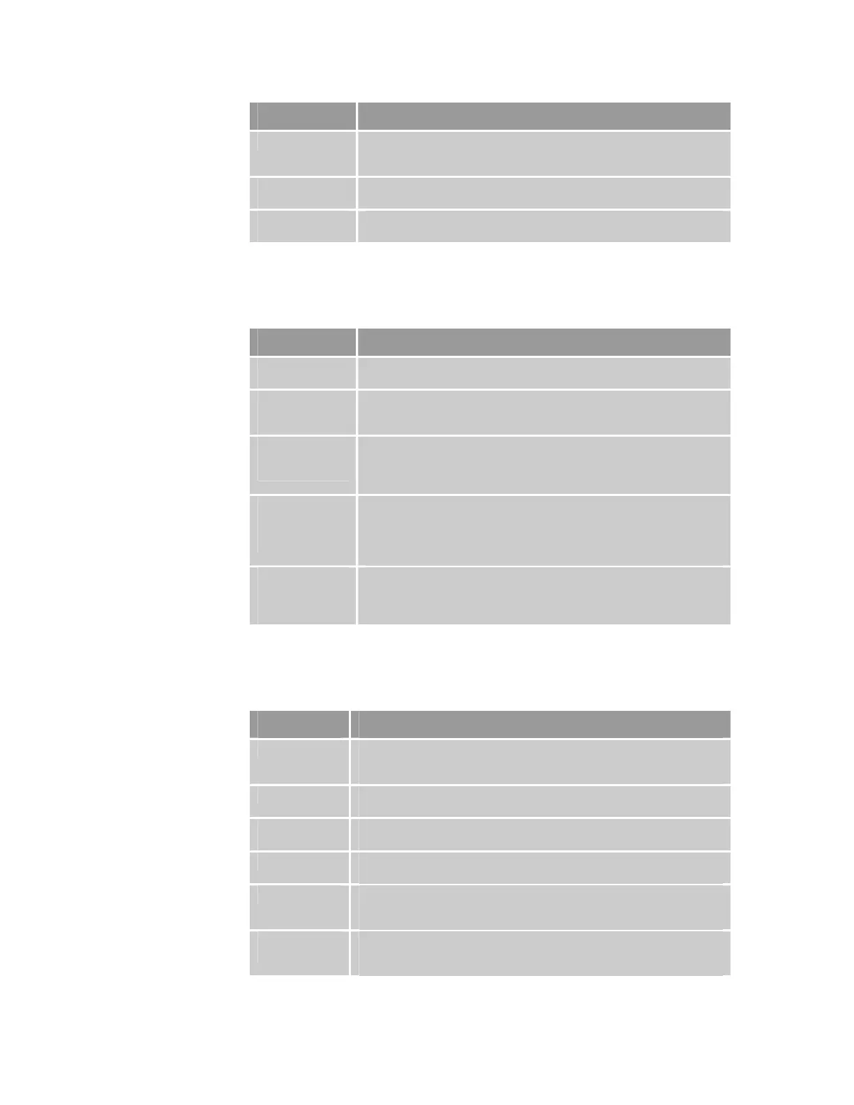
App H – general Removed statements that “ACR90x0” refers to ACR9030 and ACR9040
only. (“ACR90x0” now designates the ACR9000, ACR9030, and
ACR9040.)
App H –
Communications
Corrected color (added Amber) on Ethernet Status LEDs drawing
(Figure 46).
App H – Hall
Sensors
Corrected Figure 49 by switching motor wire labels V and W.
Revision F Changes
This document, 88-022337-01F, supersedes 88-022337-01E. Additions,
clarifications and corrections are as follows:
Topic Description
ACR User’s
Guide title change
Updated all references to the ACR User’s Guide to the new title, ACR
Command Language Reference.
Compatible
Parker Hannifin
Products
Clarified that ACR9000 is not compatible with EPL drives; added
ACR9030 and ACR9040.
Enable Connector
(Specifications
chapter)
Redesigned section; added warning regarding sharing power supply
between Motion Enable function and inductive loads such as brakes,
solenoids, contactors, relays; added polarity to Equivalent Circuit for
Enable Connector schematic.
Enable
Connection
(Installation
chapter)
Expanded section; added warning regarding sharing power supply
between Motion Enable function and inductive loads; added schematic
with loop-back diode for shared power supply; added information
regarding Parker- and Parker Daedal-build equipment from Tech
Bulletin (TB421).
Motion-Related
Error Messages
(Troubleshooting
chapter)
Added information regarding Motion Enable Input Open to Table 61
(error messages); added section Motion Enable Input Open.
Revision E Changes
This document, 88-022337-01E, supersedes 88-022337-01D. Additions,
clarifications and corrections are as follows:
Topic Description
ACR9040 Added dimensional drawing, and electrical and mechanical specifications
to Chapter 2 Specifications. Added mounting and clearance drawings to
Chapter 3 Installation.
ACR9030 Drawings and electrical/mechanical specifications were included in those
for ACR9000.
ETHERNET
Powerlink
Added Appendix H—ETHERNET Powerlink description, specifications,
instructions, and troubleshooting.
Table 39 Added box surrounding pins for Drive Enable – and + for Compax3
pinouts to indicate requirement for twisted pair.
Table 42 Added box surrounding pins for Drive Enable – and +, and for Drive
Reset – and +, for Gemini Stepper pinouts to indicate requirement for
twisted pair.
Tables 47 and
49
Corrected cable colors for CANopen pins 2, 7, and 3 to white, blue, and
black, respectively, (from white-blue, blue-white, and white-orange,
respectively.)
12 ACR9000 Series Hardware Installation Guide
www.comoso.com

 Loading...


