retaining
the coolant for
íurther
use if
antifreeze has been
added.
1 Remove the spaÍk
plug
leads,
spark
plugs
and
dicf rihr rfnr nrn
2
Remove the
top radiator
hose. rocker lubrication
pipe
and the
Ían
belt.
3 Disconnect from the
cylinder head the lower
radiatoÍ hose
and the
heater
connection.
4 Remove the
petrol
Íeed
and the distributor vacuum
lines,
disconnect the accelerator
and choke controls
at the carburetter and
remove
the
air cleaner and the
rocKer cover.
5 Remove
the carburetter and inlet
pipe
with
the
difÍuser.
6 Uníasten the exhaust flange,
the
front
mufÍler
attachment
collar and the sliding lug
of
the
generatoÍ
to cylinder head.
7
Disconnect
the electrical leads
to the magnetic
Ían.
8 Refer to FIG
1:6
and remove
the cylinder
-head
attaching
bolts
Nos.
8 and 12.
9
Fit
cylinder head
guides,
8.01 15,
into
the holes
vacated
by bolts I and
12
and
screw in
completely.
The
guides
have a knurled end fitting
with a leÍthand
thread which should
unscrew as soon as the
guide
comes
level with
the top of the rocker
gear
bearing.
10 Remove
the
remaining
cylinder head bolts
and
rocker
attaching nuts and withdraw
the rocker assembly
and
pushrods,
cylinder head and
gasket.
11 Lock
the cylinder liners
by
means
of the locking
screws
8.01 04D as shown in FIG 1 :7. lf
the
soecial
screws
are not available
a
large
washer may be used
in
conjunction
with a spacer
and a cylinder head bolt.
BeÍore replacing
the cylinder head
careÍully
clean
the
joint
faces
on the cylinder
block and
the cylinder
head.
Ensure
that both faces
are true. The
maximum
out of
true
tolerance is .05mm.
Should this tolerance
be
exceeded
the cylinder
head
joint
face may be surfaced
providing
the
minimum
overall depth
of the cylinder
head is
not
reduced below
91
.5mm;|.15.
The
cylinder block.loint
face
should never
be machined,
The
cylinder head
gasket
is
made
oÍ an asbestos
sheet
set between two sheets
oí
galvanized
iron. As from
September
1960,
the setling
width at both
ends oÍ
the
.ioint
has
been
reduced from
3 to
2mm. In
addition,
the
setting
at
the
rear end has been interrupted,
in order
to
improve
the
elasticity of the
gasket.
The
corners oÍ
the
gasket
are cut
in
order to
permit
measuring with
a set
oÍ
shims the thickness
of the
gasket
under load.
Thickness
of the
gasket
under
'1
500
kg
load,
equal
to
normal
torque
loading
oí the
cylinder head, should
be
1.5mm
+.1.
BeÍore
placing
the
gasket
on the
cylinder block, coat
the
gasket
on both sides with light
grease
or engine
oil.
Replace the
cylinder head in
the
following
manneÍ:
1
Remove
the cylinder liner locking
screws and
place
the
cylinder
head
gasket
in
position
on the
cylinder
block.
The
cylinder head
gasket
should be
fitted
wirh
the
marking DESSUS
Íacing
upwards. Make
sure that
the crankshaft is not rotated
while
the liners are
not locked
in
position
with the retaining
screws.
2 Place
the
cylinder head in
position
on the cylinder
block
(see
FIG 1 :8)
and
Íit
Nos. 3 and 7 retaining
bolts
(see
FIG 1:6).
Assemble the
pushrods
and rocker
assembly
and fit the remaining
cylinder head
bolts and
P404
)
"r/
l(
I
FIG
1 :4
Showing
the
position
of the engine
mounts
and the angular disposition oÍ the engine in the
car
FIG 1 :5
Method of slinging
the engine
@o @
e
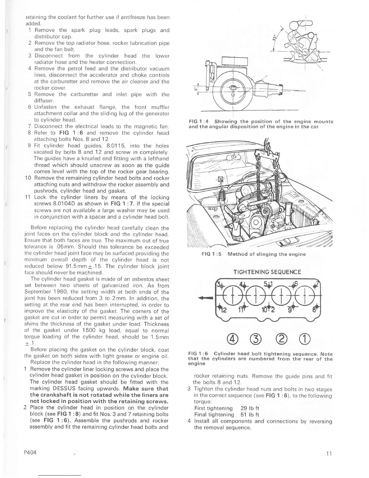
FIG
1 :6
Cylinder head
bolt tightening
sequence.
Note
that the
cylinders
are
numbered Írom
the
rear
of
the
engrne
rocker
Íetaining
nuts.
Remove the
guide
pins
and
fit
the
bolts 8
and
12.
3
Tighten
the
cylinder head nuts
and
bolts
in
two stages
in
the correct
sequence
(see
FIG 1 :6),
to the Íollowrng
toroue:
First
tightening 29 lb ft
Final
tightening
51
lb ft
4 Install
all components and
connections
by reversing
the removal
sequence.
11
TIGHTENING SEQUENCE
í+:''o+i

 Loading...


