\hb
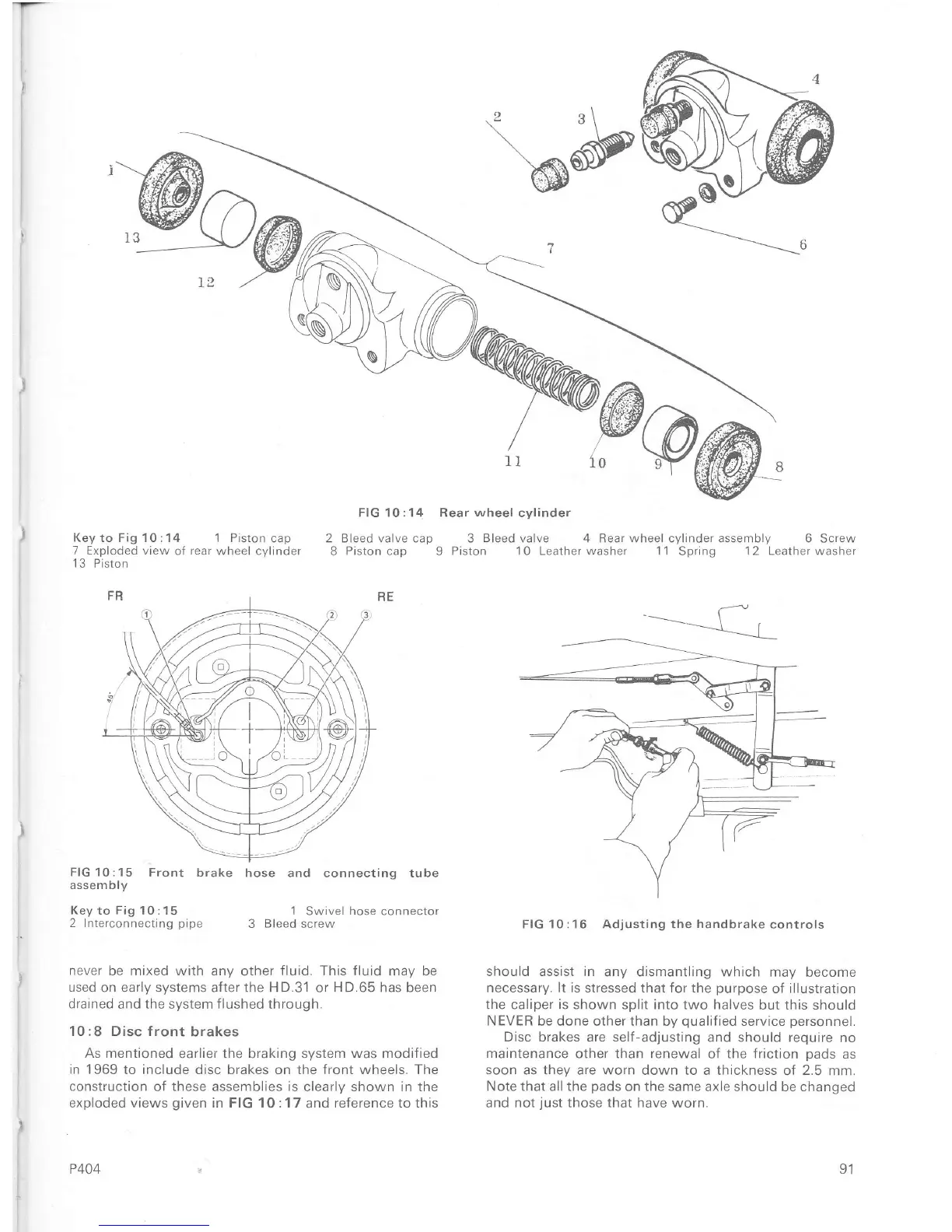
FIG 10:14 Rear
wheel
cylinder
2 Bleed valve cap 3
Bleed
valve 4 Rear wheel cylinder assembly 6 Screw
8
Piston cap
9
Piston 1
0
Leather washer 1'1
Spring
1 2 Leather washer
J
r^r
)
Key to Fig 1 0 :1 4 1 Prston
cap
7 Exploded view
oÍ
rear
wheel cylinder
1
3 Piston
FlG10;15
Front brake
assembly
Keyto Fig
10:15
2 Interconnecting
pipe
hose and connecting tube
1
Swivel
hose
connector
3
Bleed
screw
FIG 10:16 Adjusting the
handbrake
controls
should assist in
any dismantling which may
become
necessary. lt is stressed that Íor the
purpose
of illustration
the caliper
is
shown split into two halves
but this should
NEVER be done other than
by
quaiiÍied
service
personnel.
Disc brakes are self-adjusting
and should require
no
maintenance other than renewal of the friction
pads
as
soon
as
they
are
worn
down to a thickness
of
2.5
mm.
Note that all the
pads
on
the same
axle should be changed
and
not
iust
those that have
worn.
never
be mixed with any other
fluid.
This fluid may be
used
on early systems aÍter the HD.31 or HD.65 has been
drained
and
the
system
flushed
through.
10 :8 Disc front
brakes
As mentioned
earlier the braking
system was
modified
in 1969
to include disc brakes on the front wheels. The
construction
of
these
assemblies
is
clearly shown in the
exploded views
given
in FIG 10:17
and
reference to this
P404 91

 Loading...


