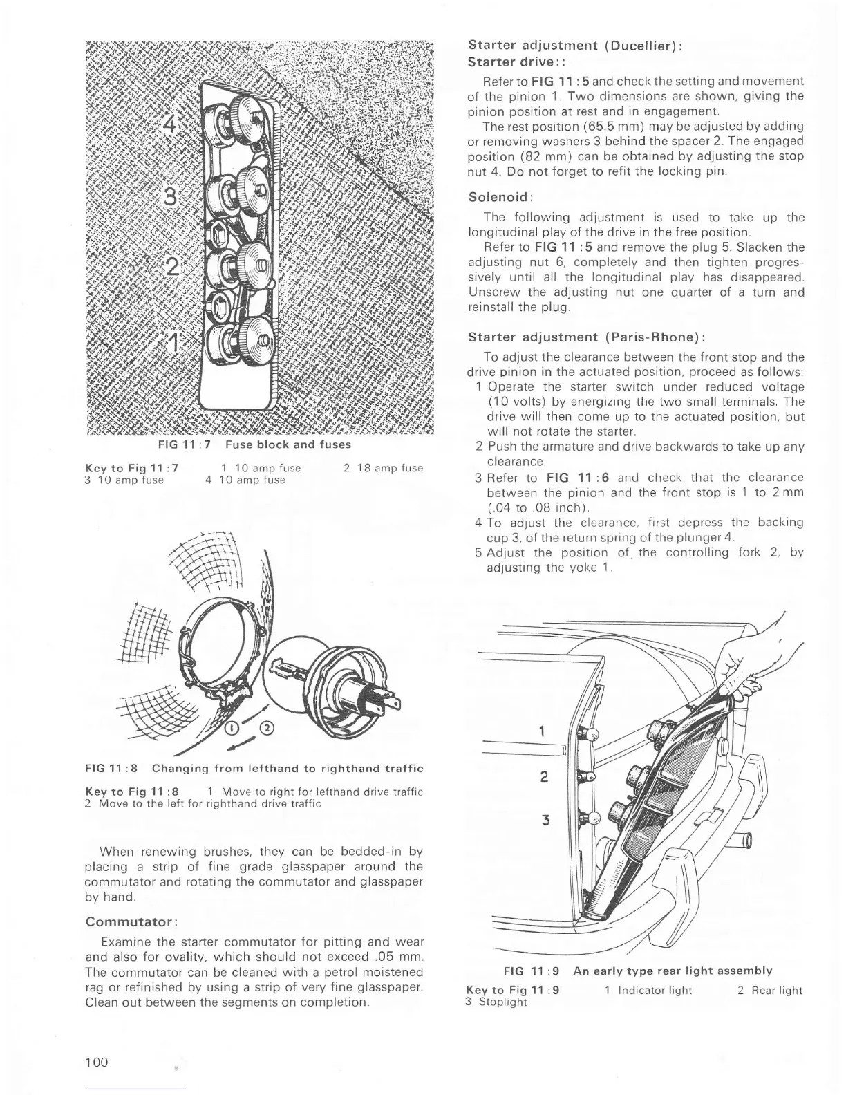
FIG 11:7
Key
to
Fig 11 :7
3
10ampÍuse 4
Fuse block and fuses
1
10
amp Íuse 2
18
amp
fuse
1
0
amp Íuse
Starter adjustment
(Ducellier)
:
Sta
rter d
rive : :
ReÍer to
FIG 1 1
:
5 and check
the setting and movement
of
the
pinion
1. Two dimensions are shown,
giving
the
pinion position
at rest and
in
engagement.
The
rest
posit;on (65.5
mm) may be adjusted by adding
or removing
washers 3 behind the
spacer 2. The engaged
position (82
mm) can be obtained
by adjusting
the stop
nut 4. Do not
forget to reÍit the
locking
pin.
Solenoid:
The following adjustment is
used
to
take up the
longitudinal
play
of the drive
in
the
Íree
position.
Refer to FIG 11 :5
and
remove
the
plug
5.
Slacken the
adlusting nut 6, completely and then tighten
progres-
sively
until
all
the
longitudinal
play
has disappeared.
Unscrew the ad.justing nut
one
quarter
of
a
turn and
reinstall
the
plug.
Starter adjustment
(
Paris-Rhone)
:
To adjust the clearance between the front
stop and the
drive
pinion
in the
actuated
position,
proceed
as
follows:
l
Operate
the
starter switch under reduced voltage
(10
volts) by energizing the two small terminals, The
drive
will then
come up
to the
actuated
position,
but
will not
rotate
the starter.
2 Push
the armalure and
drive backwards
to take
up any
clearance.
3 ReÍer to
FIG 11:6 and check that
the clearance
between
the
pinron
and
the front stop
is 1 to
2
mm
(.04
to
.08 inch)
4
To adjust
the clearance,
first
depress
the backing
cup 3, oÍ the
return
spring oÍ
the
plunger
4.
5 Adjust
the
position
of
the controlling
fork
2,
by
adjusting
the
yoke
'1
.
FIG
11 :9 An
early
type
rear light assembly
Key to Fig 11 :9 1 Indicator light 2
Rear
light
3
Stoplight
FIG 11 :8 Changing from
leÍthand
to righthand traffic
Key
to
Fig 11 :8 1
Move
to right for lefthand
drive
traffic
2 Move to the
leÍt for righthand
drive trafÍic
When renewrng brushes,
they can be bedded-in by
placing
a strip of
Íine
grade glasspaper
around the
commutator and
rotating the commutator and
glasspaper
bv
hand.
Commutator:
Examine
the starter commutator
Íor
pitting
and wear
and also Íor ovality,
which
should
not exceed
.05
mm.
The commutator can be cleaned
with
a
petrol
moistened
rag or refinished by using
a
strip of
very fine
glasspaper.
Clean out between the segments on
completion.
100

 Loading...


