FIG 7 :1 Engaging
puller
in
centre
bearing
Key
to
Fig 7:1 1 Centre
bearing cage 2 Puller finger
FIG
7 :2
Removing the bearing
Key to Fig 7 :2 B Backing washer
spacer D
Wrench
C Sheet
metal
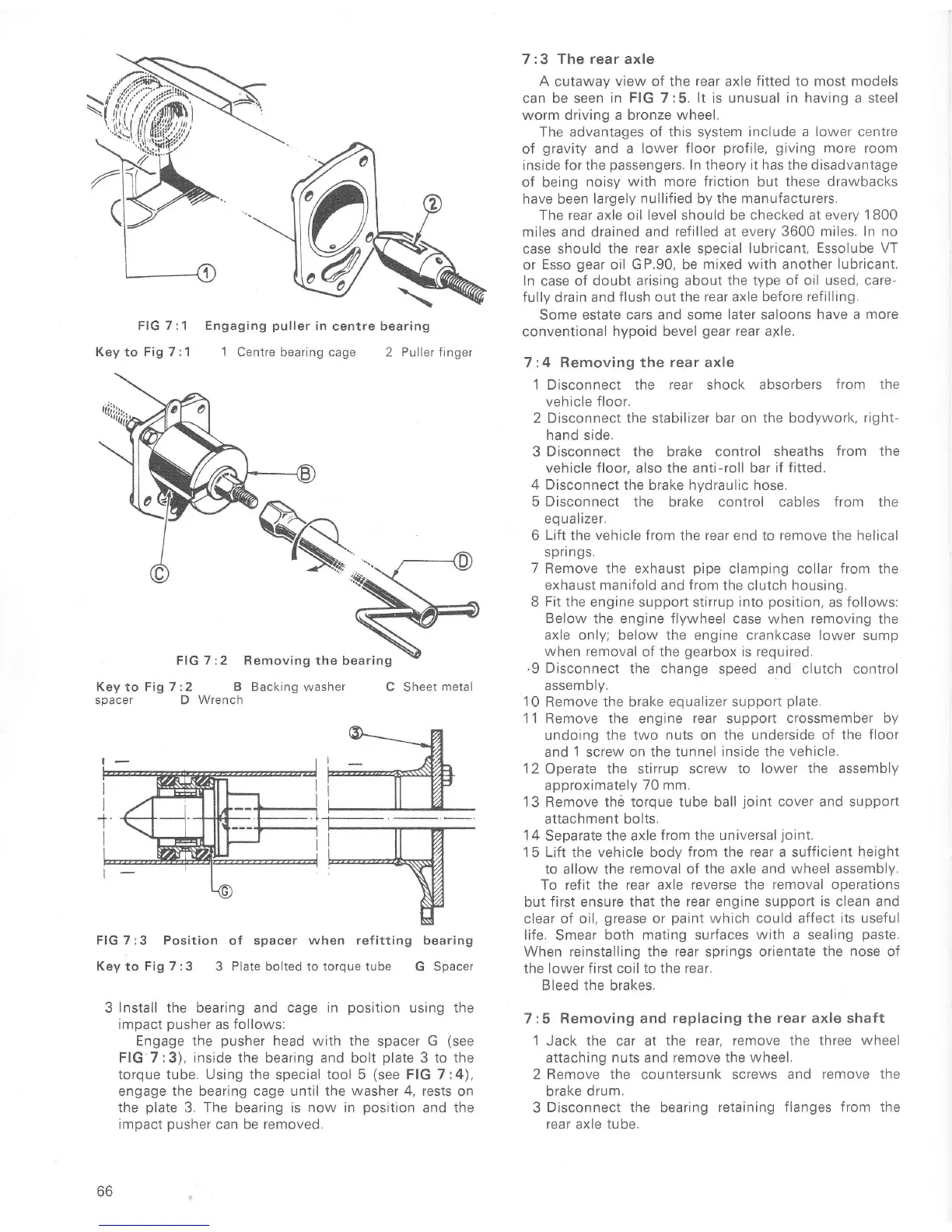
FIG 7 :3 Position
oÍ
spacer when ref itting bearing
Key to Fig
7 :3
3 Plate bolted to torque tube
G
Spacer
3
Install
the bearing and cage in
position
using the
rmpact
pusher
as follows:
Engage the
pusher
head with the spacer G
(see
FIG
7:3), inside the
bearing and bolt
plate
3
to the
torque tube. Using the special tool 5
(see
FIG 7:4),
engage
the bearing cage until the washer 4, rests
on
the
plate
3,
The
bearing
is now in
position
and
the
impact
pusher
can be removed.
66
7:3
The rear
axle
A
cutaway
view
of
the rear
axle
fitted to most models
can be seen
in FIG 7:5. lt is unusual in having a steel
worm driving a bronze wheel.
The advantages of this system include a lower centre
of
gravity
and a
lower floor
profile,
giving
more
room
inside for the
passengers.
ln theory it has
the
disadvantage
of
being
noisy
with more friction
but
these drawbacks
have been
largely nullified by the manuÍacturers.
The rear axle oil
level
should be
checked at every 1 800
miles
and drained and refilled at every
3600 miles, In no
case should the
rear axle special lubricant,
Essolube VT
or Esso
gear
oil
GP.90,
be
mixed with another
lubricant.
In
case
of doubt arising about
the type of oil used, care-
fully
drain
and flush out
the rear axle beÍore reÍilling.
Some estate cars and some
later saloons
have
a
more
conventional
hypoid bevel
gear
rear
a1le.
7:4 Removing the rear axle
1 Disconnect the rear shock absorbers
from the
vehicle floor.
2
Disconnect the stabilizer bar on the bodywork,
right-
hand side.
3
Disconnect
the brake control
sheaths
from the
vehicle
floor,
also the anti-roll
bar iÍ fitted.
4 Disconnect
the brake hydraulic hose,
5 Disconnect the
brake control cables Írom the
eo
ualizer,
6
LiÍt
the
vehicle
from ïhe rear end to Íemove the helical
spflngs.
7
Remove the
exhaust
pipe
clamping collar Írom the
exhaust manifold and f rom the
clutch
housing,
8 Fit the engine support stirrup into
position,
as
follows:
Below the engine flywheel case
when
removing
the
axle only; below the
engine crankcase lower sump
when removal
of the
gearbox
is required,
,9
Disconnect
the change speed
and
clutch
control
assembly.
10
Remove the brake equalizer
support
plate.
'1
1
Remove the engine
rear
support
crossmember by
undoing
the two nuts on the underside of
the floor
and
1
screw
on the tunnel
inside
the
vehicle.
12
Operate
the stirrup screw to
lower the assembly
approximately
70 mm.
13 Remove thè torque tube ball
joint
cover and support
attachment bolts,
1
4
Separate
the axle
from the universal
joint.
15 Lift the vehicle body from the
rear
a sufficient
height
to allow the
removal
oÍ
the axle and wheel assembly,
To refit the rear axle
reverse the removal operations
but Íirst ensure
that the Íear engine support
is
clean and
clear of oil,
grease
or
paint
which
could affect its useÍul
life. Smear
both mating surfaces
with
a sealing
paste.
When reinstalling
the rear
springs orientate
the
nose
of
the lower
first
coil
to the rear,
Bleed
the
brakes,
7:5 Removing and replacing the
rear axle
shaft
1
Jack the car at
the rear, remove the three
wheel
attaching
nuts and remove the
wheel,
2 Remove the countersunk screws
and remove the
brake
drum.
3
Disconnect the
bearing
retaining
flanges from the
rear axle
tube,

 Loading...


