Key to
Fig 6:1
synchronrzer
gear
BA7. Remove the
rear retaining ring from the clutch
slave cvlinder.
Place a suitable support under
the
gearbox
and then
remove the engine
rear mounting bolts.
Disconnect the
rear
dampers
from the axle tubes and the
stabilizer
bar from the
lefthand
axle
tube.
lÍ thermostable brakes are
f itted the compensator
spring
must
be detached
from the stabilizer, but
do not
slacken the nut securing
the
clamp
spring assembly.
Disconnect the rear anti-roll bar
from the connecting
links
and
remove the four bolts securing
the torque tube
ball
joint.
Note that it
may
be
necessary to free the body
to
gain
access
to the two upper bolts.
Jack uo the reaÍ
end
of
the car and
remove
the
rear
spfl ngs.
Move the rear axle assembly toward
the
rear
to
clear the
torque tube at the universal
joint
splines.
Remove the rear engine
mounting and
the clutch
opeÍating rod, Remove
three Allen screws
securing
the
clutch
housing and withdraw
the
gearbox
to the rear.
On
BA7
gearboxes
the slave cylinder
should be
removed
from
the
front, it is not
necessary to disconnect
the
hydraulic
pipe.
Refitting
the
gearbox:
This
is
carried out by
reversing the
removal
procedure,
paying
attention to the
following
points:
In
order to ensure
the alignment oÍ the
gearbox,
the
front cross
piece
support must be slackened
before
recoupling
the differential.
52
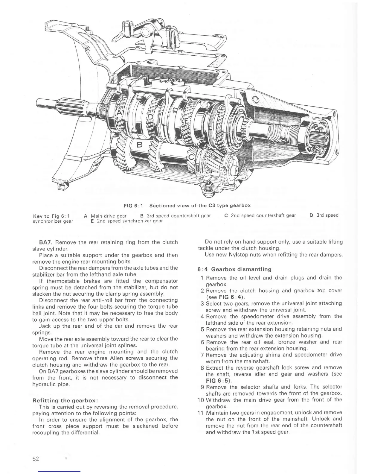
C
2nd speed countershaÍt
gear
D 3rd
speed
Do
not rely on hand support only,
use a
suitable liÍting
tackle
under the clutch housing.
Use new Nylstop nuts when refitting
the
rear
dampers.
6
:4
Gearbox
dismantling
l
Remove
the oil level and
drain
plugs
and
drain the
gearbox.
2
Remove the clutch
housing
and
gearbox
top cover
(see
FIG 6:4).
3 Select two
gears,
remove
the universal
joint
attaching
screw and
withdraw the
universal
joint.
4 Remove
the speedometer
drive assembly
from the
lefthand side
oÍ the rear extension.
5 Remove
the rear extension
housing
retaining nuts and
washers
and
withdraw the extension
housing.
6 Remove
the rear oil seal,
bronze
washer
and
rear
bearing
Írom the rear extension
housing.
7 Remove the adjusting
shims and speedometer
drive
worm from the mainshaft.
8
Extract the reverse
gearshaft
lock
screw
and remove
the
shaft,
reverse idler and
gear
and
washers
(see
FIG 6:5).
9 Remove
the selector shafts
and
forks.
The
selector
shaÍts are
removed
towards
the front of
the
gearbox.
10
Withdraw
the
main
drive
gear
from the
front
of
the
gearoox.
1 1 Maintain
two
gears
in
engagement,
unlock and
remove
the nut on
the Íront of
the mainshaft.
Unlock and
remove the
nut Írom the
rear end of
the countershaft
and
withdraw the
1st
speed
gear,
FIG 6:1 Sectioned
view of
the C3 type
gearbox
A Main drive
gear
B 3rd
speed countershaft
gear
E 2nd speed synchronizer
gear

 Loading...