<gï1)
)
c
{fft
ob
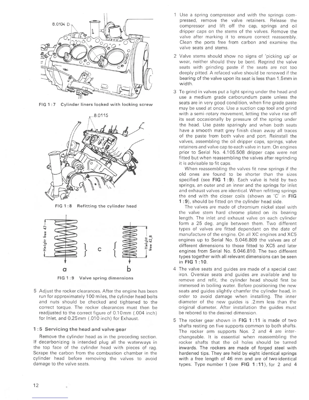
FIG
1 :9
Valve spring dimensions
5 Adjust
the
rocker
clearances. After
the engine has been
run Íor
approximately 1
00
miles,
the cylinder head
bolts
and nuts
should be checked and
tightened to the
correct torque. The rocker
clearances must
then be
readjusted to
the correct figure
of 0.10mm
(.004
inch)
Íor
Inlet, and
0.25mm
(.01
0 inch) Íor Exhausr.
1 :5
Servicing the head
and
valve
gear
Remove
the cylinder head
as
in
the
preceding
section.
lf
decarbonizrng is intended
plug
all the waterways
in
the top face oÍ
the cvlindeÍ head with
pieces
of rag.
Scrape the
carbon
from
the
combustion chamber
in
the
cylinder head
before removing
the valves
to avoid
damage to
lhe valve seats.
12
Use a spring compressor and with the springs com-
pressed,
remove
the
valve
retainers. Release
the
compressoÍ
and
lift
off
the
cap, springs and
oil
dripper caps on
the stems of the
valves.
Remove
the
valve
aÍter
marking it
to ensure correct reassembly.
Clean the
ports
free from carbon and examine
the
valve seats
and stems.
Valve stems should
show no signs of
'picking
up'
or
weaÍ, neither should
they be bent. Regrind
the
valve
seats
with
grinding
paste
if
the seats
are
not
too
deeply
pitted.
A refaced valve should
be
renewed if
the
bearing of the valve
upon its
seat
is less
than 1.5mm in
width.
To
grind
in valves
put
a
light spring
under the head and
use a medium
grade
carborundum
paste
unless the
seats are in very
good
condition, when fine
grade paste
may
be used at once. Use a suction cap tool and
grind
with
a semi-rotary
movement, letting
the
valve rise
ofÍ
its seat occasionally by
pressure
of the spring under
the head. Use
paste
sparingly and when
both seats
have
a
smooth matt
grey
finish
clean
away all
traces
of the
paste
from
both
valve
and
port.
Reinstall the
valves, assembling
the oil dripper caps, springs, valve
retainers and valve
cap to each
valve
in turn.
On
engines
prior
to Serial No, 4.105.508 dripper
caps were
not
Íitted
but when reassembling
the
valves
after regrinding
it is
advisable to f it caps,
When reassembling
the
valves fit
new springs iÍ the
old ones are found
to
be shorter
than the sizes
specified
(see
FIG 1:9). Each valve is
held by two
springs,
an outer and an
inner
and the springs Íor inlet
and exhaust valves
are
identical.
When refitting springs
the end
with
the closer coils
(shown
as
'C'
in
FIG
1 :9), should
be
fitted
on the cylinder head side.
The
valves are made of
chromium
nickel
steel with
the
valve
stem hard chrome
plated
on
its bearing
length. The inlet
and exhaust
valve
on each
cylinder
form
a 25 deg.
angle
between
them.
Two
difÍerent
types
of
valves
are
Íitted
dependant
on
the date
of
manufacture of the engine.
On
all XC
engines and
XC5
engines up to
Serial
No.
5.046.809 the valves
are of
diÍferent dimensions
to those
Íitted
to
XC5
and later
engines from Serial No. 5.046.81
0.
The
two different
types together with
all
relevant
dimensions can
be seen
in FIG
1
:10.
The valve
seats and
guides
are made of
a special cast
iron.
Oversize seats and
guides
are available and
to
remove
and
refit,
the cylinder head should first be
immersed in
boiling water. Before
positioning
the new
seats
and
guides
slightly chamÍer the cylinder head,
rn
order to avoid
damage
when installing. The inner
diameter of
the new
guides
is
,2mm
less
than the
original
diameter.
AÍter installation
the
guides
must
be rebored
to the desired dimension.
ïhe
rocker
gear
shown
in
FIG 1:11
is made
of
two
shaÍts
resting
on
five
supports common
to both shafts.
The
rocker arm suDoorts Nos. 2
and 4 are inter-
changeable. lt is essential when reassembling
the
rocker shafts that
the oil
holes should be turneo
inwards. The rockers are made of forged
steel
with
hardened tips. They
are
held
by eight identical springs
with
a
free length
of
46
mm and are of
two identica.
types; Type
number
1
(see
FIG 1:11),Íor
2 and
4
FIG
1 :7
Cylinder
liners locked with locking screw
FIG 1:8 ReÍitting
the cylinder head

 Loading...


