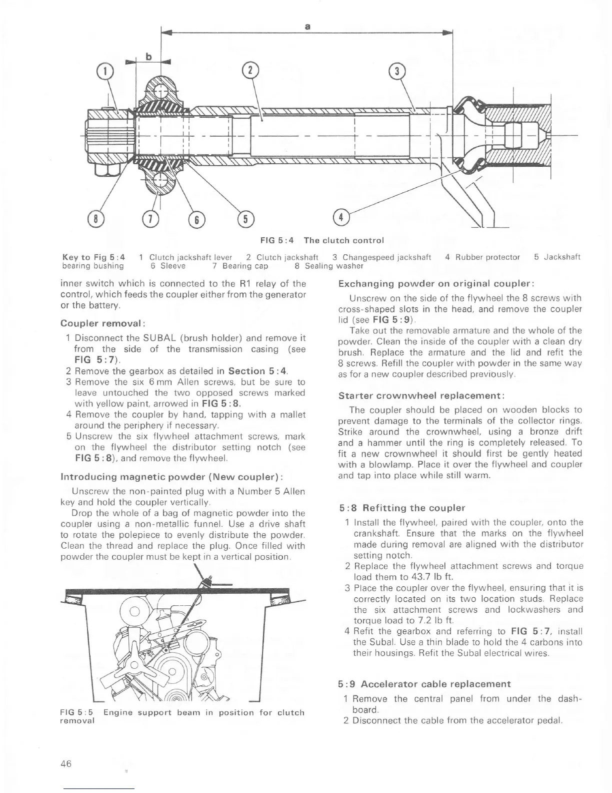
FIG
5:4 The clutch control
Key to Fig 5 :4 1 Clutch
jackshaft
lever 2 Clutch
jackshaÍr
3 Changespeed
jackshaft
bearing bushing 6 Sleeve 7 Bearing cap
8 Sealing
washer
inner
switch
which is
connected to the
R1
relav
of
the
control, which feeds the
coupler
either
Írom the
generator
or the
battery.
Coupler removal:
1 Disconnect
the SUBAL
(brush
holder)
and
remove it
from
the side of the transmission casing
(see
FIG
5
:7).
2 Remove
the
gearbox
as detailed in
Section 5:4.
3
Remove the
six
6
mm
Allen
screws, but be sure to
leave untouched the two opposed
screws
marked
with
yellow paint,
arrowed in FIG 5 :8.
4 Remove the
coupler by
hand,
tapping
with
a mallet
around the
periphery
if necessary,
5 Unscrew
the
six Ílywheel attachment screws, mark
on the
flywheel
the distributor setting notch
(see
FIG
5
:8),
and remove the
flywheel.
Introducing magnetic
powder
(New
coupler):
Unscrew the non-painted
plug
with
a Number 5 AIlen
key and hold the coupler vertically.
Drop
the
whole
of a bag oÍ
magnetic
powder
into the
coupler using a non-metallic funnel.
Use a drive shaft
to rotate the
polepiece
to
evenly distribute
the
powder.
Clean
the
thread and replace the
plug.
Once
filled
with
powder
the coupler must be kept in a vertical
position.
4 Rubber Drotector
5
Jackshaft
Exchanging
powder
on
original
coupler:
Unscrew on the side of
the flywheel the
8
screws with
cross-shaped
slots in the head, and íemove the coupler
lid
(see
FIG 5 :9).
Take out the
removable
armature and
the whole
of
the
powder.
Clean
the inside
oÍ
the coupler with a clean
dry
brush, Reoiace
the
armature and
the lid
and
reÍit the
B
screws. Refill lhe coupler with
powder
in the same
way
as
for
a new
coupler
described
previously.
starter crownwheel
replacement :
The
coupler
should be
placed
on wooden blocks to
prevent
damage to the teíminals
of the collector
rings.
Strike around
the crownwheel, using a
bronze drift
and a
hammer until the ring
is
completely
released. To
fit
a new crownwheel
it should
first
be
gently
heated
with
a
blowlamp. Place it over
the flywheel and coupler
and tap
into
place
while still
warm.
5
:8 Refitting the coupler
1 Install
the
flywheel,
paired
with the coupler. onto the
crankshaft.
Ensure that the marks on
the flywheel
made during
removal are aligned
with the
distributor
setting
notch.
2 Replace
the flywheel
attachment
screws and
torque
load them
to 43.7
lb Ít.
3
Place
the coupler
over the
flywheel,
ensuring
that rt is
correctly
located on its two
location
studs.
Replace
the
six
altachment screws and
lockwashers and
torque load to
7.2 lb Ít.
4 Refit
the
gearbox
and
reÍerring to FIG
5:7,
install
the
Subal.
Use
a
thin
blade to hold the 4 carbons
into
their housings. Refit
the Subal electrical wires.
5:9 Accelerator cable
replacement
1
Remove
the central
panel
from
under
the
dash-
board.
2 Disconnect the cable from the
accelerator oedal.
FIG 5:5 Engine support
beam
in
position
Íor
clutch
removal
46

 Loading...


