9
:9 Ref itting
the
rack
and
pinion
unit
1 Position the rack
assembly against
the
crossmember
and fit the two attachment screws. Tighten to
a
torque
of
22 Ío
32
lb
ft. lt will
be
necessary to
dis-
connect
the Íront engine
mountings
in
order tb apply
a torque wrench to these screws. Reconnect the
mountings after tightening the
rack
assembly screws.
2 Reconnect the steerrng at the flexible coupling
and
tighten the
yoke
bolt
to a torque
of
5,5
to
9lb ft. Lock
the
bolt
by
peening.
3
Fit the steering connecting links in
the
steering arms
and tighten
the
ball
joint
nuts to 36 to
40 lb
ft and
lock with splitpins..
4
Bring the
right
hand connecting link into
position
and
Íit
and tighten
the eye bolt and
nut.
5
Adjust the Íront
wheel alignment
to .079+ .039 inch
toe-in
by screwing
the
ball
head nut
on the
lefthand
connecting
link
in or out. Tighten the locknut
against the ball head nut.
6 Fit and secure the
rubber
boots on the rack housrno
and connecting links-
7 Check the installation by turning the steering wheel
Írom
lock
to
lock.
8 Check
the
steering
wheel
position
in the straight-
ahead
position
and correct as
necessary
by
removing
and
repositioning the
wheel.
9:10 Road testing the steering
Drive the car at about 30
mile/hr
and
then
take
vour
hands
ofÍ the
steering
wheel. The
car should maintain
a straight course. lÍ the road is crowned, it
may cause
rhe car to wander towards the low side of
the
road
and.
thereÍore, it may be necessary to
make
this
test straddled
over the centre
line.
Uneven
front
end angles will cause
the car to
wander
to one side.
Hold
your
hands lightly
on
the
steering wheel at about
30
mile/hr to check whether
any
shocl<s
are being trans-
mitted
back
to the steering
wheel.
A.constantly
jiggling
wheel inciicates that the front wheels are out of
balance.
Apart from being tiring to the driver on.a
long
journey
this movement
is
bound to accelerate wear
on everv
moving
part
of the front end.
With the car moving at about 25 milelhr turn
through
90 deg. and
then release the
steering
wheel. lt
should
come back to the straightahead
position
without any
assistance
from the
driver.
lÍ it
does not
il indicates
binding
in the linkage, insufÍicient caster
or
insufficient
steering
axis inclination.
To
check
for misalignment,
inspect the front
tyres
for
uneven tread
wear.
Sharp
edges Íelt
going
one
way are
called
feather edges and are developed
Írom
sideways
scufÍing often due
to incorrect toe-in.
I
:11
Fault
diagnosis
(a)
Wheel wobble
1 Unbalanced
wheels and tyres
2
Slack
steering connections
3
Incorrect steering
geometry
4 Excessive
play
in
steering
gear
5 Weak
front springs
6 Worn hub bearings
P404
Key ro Fig
I
:12
snrms
1 Rack
damper
plunger
2 Adjusting
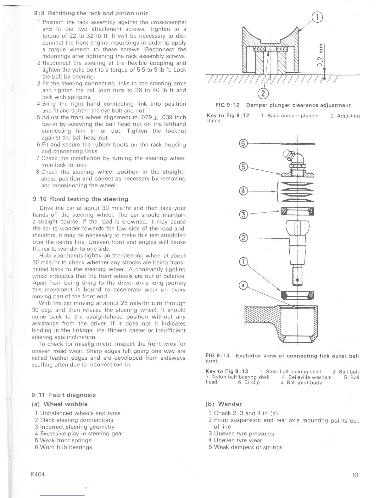
FIG
9:13 Exploded
view
of
connecting
link
outer ball
joint
Key
to Fig I :1
3
1
Steel
half
bearing shell
2 Ball bott
3 Nylon half
bearing
shell 4 Belleville
washers
5 Ball
head
6 Circlip
a
Ball
joint
body
(b)
Wander
1
Check 2,
3
and 4 in
(a)
2 Front suspension
and rear
axle mountrng
points
out
of
line
3 Uneven tyre
pÍessures
4 Uneven tyre
wear
5
Weak dampers or springs
FIG 9 :1 2
Damper
plunger
clearance
adjustment
81

 Loading...


