f
exceed
20 to
25mm
(.079
to.099 inch).
This is due
to a modiÍication
of the castellated
nut.
6
Install and tighten
the castellated
nut to a
torque of
44
to 50 lb ft.
7 Remove
the nyloc
nut and special spacer
F from
the
shock
absorber
rod.
Work the rod in and out
to check
for free sliding
and rotation
movement,
leaving the
rod
in
the
extended
position.
8 Re-install
the
pivot
bearrng
ball cage and
lubíicate
with multi-purpose
grease.
9
Insert the upper attachment
cup
(item
'l
of
FIG 8:7),
into the
rubber
protector
using
a small
quantity
of
cement
to stick the cup
inside the
protector
so that
it
will remain in
position
during
assembly.
10 Secure
the
Íubber
protector
to the
spring
lower
backing
cup
with
a
clamp
and
position
the
coil spring
on
the backing cup
(see
FIG
8
:8).
1
1 Place the shock
absorber
upper
support on
top oÍ
the
spring and
position
the safety
cup in
the upper
support
by means
of
the tab and
groove
(see
FIG
8:7).
12
Compress
the spring
assembly
with a spring
com-
pressor
and centre
in
position
on top of
the shock
absorber.
Position
the
rubber
protector
upper cup
(see
item 2, FIG 8:7).
and as
the
lower
cup
comes
to rest
on
the thrust bearing,
the
shock absorber
rod will
appear
in the saÍety
cup,
if the rod has been
main-
tained
in its
extended
position.
Failure oÍ
the
rod to
appear
in the safety
cup
will mean that
the
rod has
been
accidentally
pushed
down and
the assembly
will have to be
removed
and
re-installed
with the
rod
fully extended.
FIG 8:7
Ïhe coil
spring
prepared
for installation
FIG 8:8 The coil spring
lower thrust bearing showing
modif ied type
f rom
which the spring
backing rubber has
been deleted
Key to Fig I
:8
1 Spring backing
cup
3
Coil spring
r-ê-
O-j
--
---
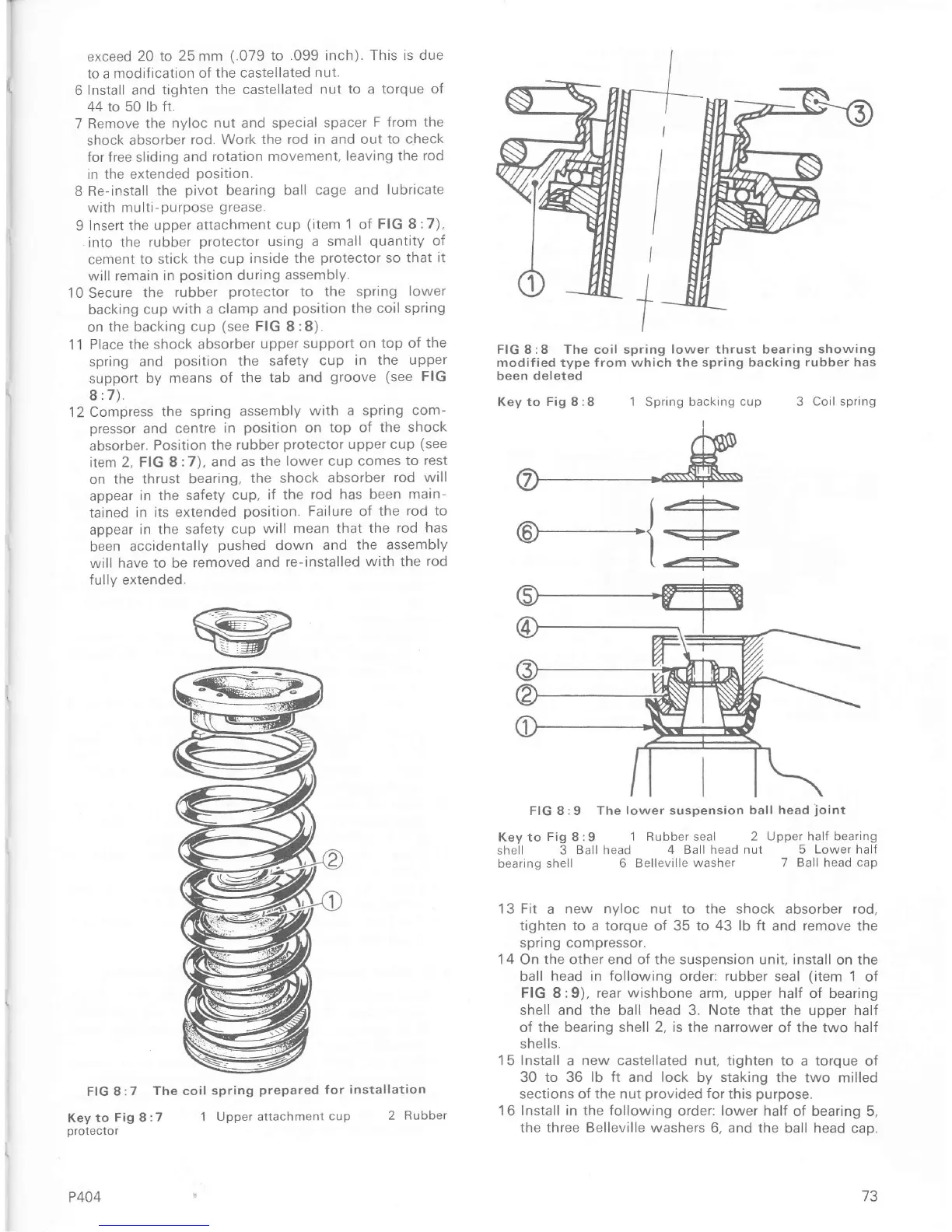
FIG 8:9 The
lower suspension
ball head
joint
Key to
Fig
8:9
I Rubber seal
2 Upper halÍ bearing
shell 3
Ball head 4 Ball head
nut 5 Lower halÍ
bearing
shell 6 Belleville
washer 7
Ball
head
cap
13 Fit
a
new nyloc nut to the shock
absorber
rod,
tighten
to a
torque of 35 to
43 lb ft
and remove the
spnng compressor.
14 On the other end oÍ the suspension unit, install
on
the
ball head in following order: rubber
seal
(item
1
of
FIG 8:9),
rear wishbone
arm, upper half
of bearing
shell and the ball
head
3. Note that the
upper
half
oÍ the bearing shell
2, is
the narrower
of the two
half
shells.
15 Install a
new
castellated nut, tighten
to a torque oÍ
30 to 36
lb
ft and lock
by
staking
the two milled
sections
of the
nut
provided
for
this
purpose.
16Install in the
Íollowing
order: lower
half of bearing 5,
the three Belleville washers 6, and the
ball head cap.
Key to
Fig 8 :7
protecto
r
P404
1 Upper attachment
cup
2 Rubber
73

 Loading...


