While doing this adlustment, the solenoid
should not
remain energized
for more than
a
few
seconds
to
avoid
deterioration of
the wrndings.
11
:5 Fuses and
fuse ratings
The electrical
circuit contains
four
fuses
which
are
installed on
a board under
the
dashboard
on
the
leÍthand
side.
The
fuses
are
numbered
1 to 4 and
protect
the
following
circuits:
Fuse
No.
1
-The
head and tail
lights, the instrument
panel
lighting and the
luggage compartment
light
(10
amp
fuse).
Fuse
No. 2 f he hanging
lamp
socket, the
parki.ng
lights,
the
roof light and the
horns
(18
amp
f
use).
Fuse No. 3-The
indicator
lights, the stoplights and
the
magnetic
fan
(10
amp
Íuse).
Fuse No.
4-The heater
and the windscreen
wiper
(10
amp
f
use).
The
layout
of
the
Íuse
box
can
be
seen
in FIG 11 :7.
From
1968
a
fuseboard containing 5
fuses is Íined.
The Íuse
rating
and
the circuits they
protect
can
be seen
from the
wiring diagrams
(see
Appendix).
11
:6 Lights
The headlights, eather Marchal, Ducellier or Cibié, are
of the
assymetric beam type. To adjust the headlights.
special checking equipment
must be
used.
The adjust'
ment
is made by removing the headlight
rim
and
Íor
the
vertical adjustment on
MaÍchal and Ducellier headlamps
the
upper adjusting screw is used and
Íor
the vertical
adlustment
on
Cibie
lamps the lower screw.
For the
lateral
adjustment on all
lamps use either
oÍ
the lateral adjusting screws
The headlamps may be easily switched over
for
driving
in
either
leÍthand
or
righthand
trafÍic.
In
order
to
reverse the assymetric beam,
the
notch
guide
lever
of
the bulb can
be
moved
sideways
(see
FIG
11 :8). Move
the
guide
to the right for
lefthand
side trafÍic and to the
left for righthand
side
traffic.
Side,
indicator
and
brake
lights:
At
the front
of
the car the side lights and
indicator
lights are housed in one double
f ilament bulb. The
parking
lights
on
both
front
wings
act
as
indicator light repeaters
when the
parking
light conïrol is switched oÍf
.
At the rear
oÍ
the car
(see
FIG 11:9),
the top light rs
the
indicator which has a
yellow
bulb.
-fhe
centre light
is the
rear light and the bottom light the brake light, both
of which
are red.
The
instrument
panel
lights
are lit when the side
or
headlamps are switched
on,
thereby acting as a
lighting
ind icator.
The roof
light
is controlled by a swiïch
actuated
when
the
front doors are opened.
This
control
can
be
over-
ridden bv a separate switch
inside the car.
11 :7 Accessories:
The electrical clock
is
permanently
fed
direct
from the
battery.
lf at
any
time the battery has been switched ofÍ or
disconnected
the clock must
be restarted.
The
SEV
windscreen rviper motor is installed under the
bonnet
(see
FIG 11 :10).
lt
is controlled from a switch on
the
dashboard,
and is
of
the selÍ-parking type, switching
off
when the blades are
in the
bottom
position.
This leaves
the windscreen unobstructed
when in the off
position.
P404
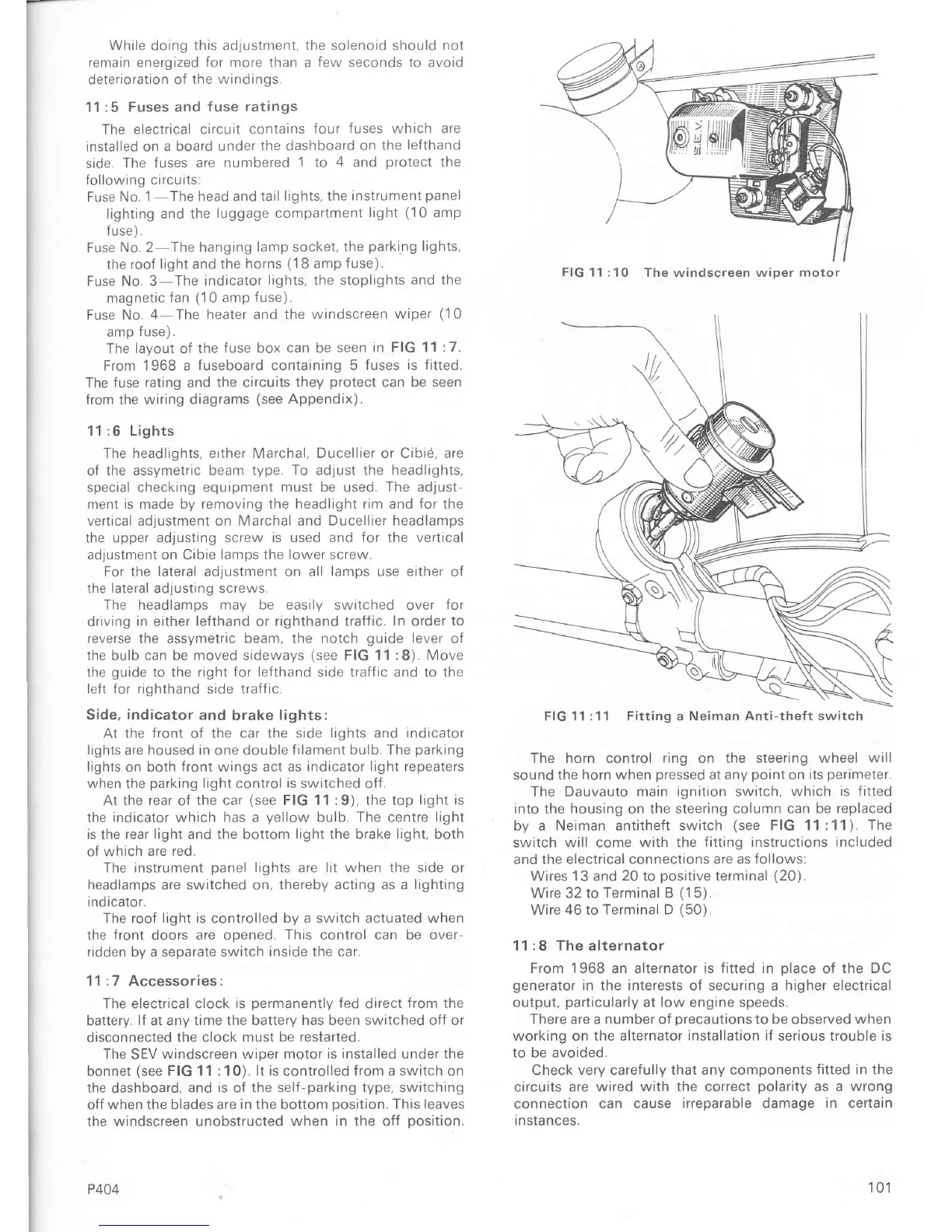
The horn control
ring
on the
steering
wheel
will
sound the horn when
pressed
at any
point
on
its
perimeter.
The Dauvauto main
ignition switch, which is
fitted
into
ïhe housing on
the
steering
column can be replaced
by a
Neiman
antitheft
switch
(see
FIG 11:11).
The
switch will come
with the fitting instructions included
and the electrical
connections are as
follows:
Wrres 13 and
20
to
positive
terminal
(20).
Wire 32 to Terminal
B
(1
5).
Wire 46 to Terminal D
(50).
11:8 The
alternator
From 1968 an alternator
is Íitted in
olace
of the
DC
generator
in
the
interests
of securing a
higher
electrical
output,
particularly
at low engine speeds.
There are a number oÍ orecautions to be observed when
working on the alternator
installation iÍ
serious trouble is
to be avoided.
check very
careÍully
that any components
Íitted in the
circuits aÍe
wired with the coÍrect
polarity
as a
wrong
connection can
cause irreparable damage in certain
i n
sïa
nces.
FIG
11 :10 The windscreen wiper motor
FIG
11:11 Fitting a Neiman Anti-theft switch
101

 Loading...


