B
Fit
the bearing cap
screws finger tight
and
withdraw
the assembly
tool. Tighten the cap screws
to the
specified toroue
of
50 to 58 lb ft.
9 Cut
off the
rubber
side
seals .020 inch
above the
crankcase
face.
1 :13
Oil
f
ilter
Clean oil for lubrication
of the engine is
provided
by the
oil Íilter, which is Íitted in
an horizontal
position
between
the
pump
and
the
lubrication
circuit
(see
FIG
1 :16).
The
filter body is made
of light alloy and is Íitted
with
a
cleanable cartridge which
should be cleaned
at each
occasion of draining the
sump.
The
capacity
oÍ the filter
is
approximately
1
pint.
On
later
cars an'Easi-change',
or
Lockheed,
disposable
Íilter
cartridge
is
used. This should
be changed every 6000
miles
(10,000
km).
The
pressure
switch, which
is fitted
onto the f ilter
body,
switches oÍf the
red
tell-tale
light
on the Íacia
panel
as
soon
as
the
oil
pressuÍe
reaches 1 O lblsq in.
1 :14 Reassembling
stripped engine
All dismantling and reassembling
operations have
been
given
in
the various Sections, so that it is
simply a matter
of
tackling the
tasks
in
the correct sequence. Always Íit
new
gaskets,
which are normally available in
complete
sets,
and
lubricate
all
running
surfaces
with clean
engine oil.
First Íit
the crankshaft, followed by the cylinder liners,
iÍ removed, and then
the
piston
and connecting rod
assemblies. Next fit
the timing
gear
housing
support, the
camshaÍt and the timing
gear.
lnstall
the flywheel and clutch, then the
oil
pump,
ensuring
correct
meshing
to enable the distributor to
be
timed.
Install
the oil sumo.
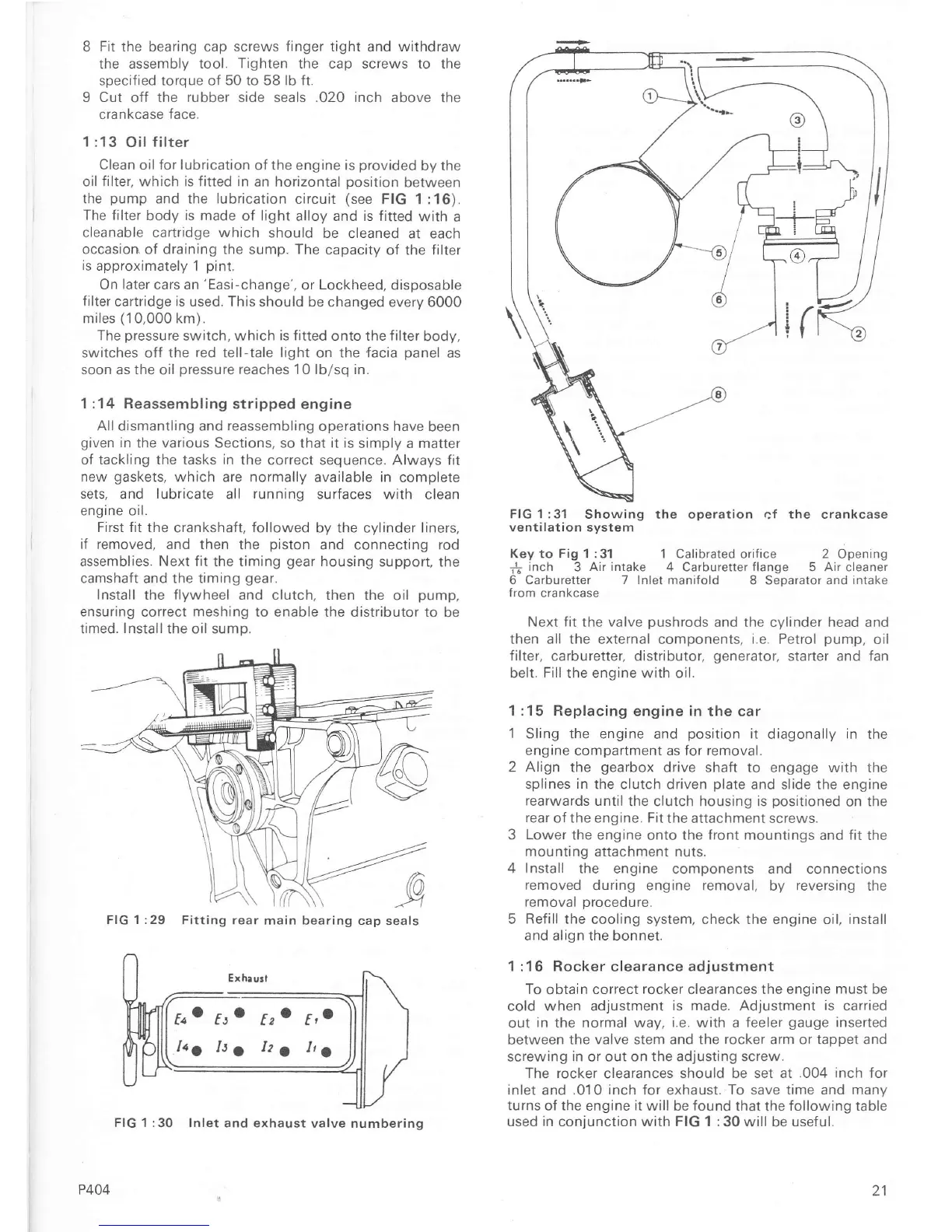
FIG 1 :31
Showing
ventilation svstem
the crankcase
Key to
Fig
1 :31 1 Calibrated oriÍice 2
Opening
{
inch
3
Air intake 4
Carburetter
Ílange 5 Air
cleaner
6 Carburetter 7 Inlet maniÍold
8 Seoarator and
intake
Írom crankcase
Next fit the valve
pushrods
and the cylinder head and
then all the external
components,
i.e. Petrol
pump,
oil
filter, carburetter, distributor,
generator,
starter and fan
belt.
Fill
the engine with oil.
1 :15 Replacing
engine in
the car
1 Sling the
engine and
position
it
diagonally in the
engine compartment as Íor removal.
2
Align
the
gearbox
drive shaft to engage with the
splines in
the clutch driven
plate
and slide the engine
rearwards until
the clutch housing is
positioned
on the
rear
oÍ the engine. Fit
the attachment screws.
3
Lower
the engine
onto the
front mountings
and
Íit
the
mounting attachment nuts.
4 Install
the engine
components and connections
removed during
engine
removal,
by
reversing
the
removal
procedure.
5
ReÍill the
cooling system, check the engine oil, install
and align the
bonnet.
1 :16
Rocker
clearance adjustment
ïo
obtain
correct
rocker
clearances the engine
must
be
cold when adjustment
is made. Adjustment
is
carried
out
in
the normal way,
i.e.
with a
Íeeler
gauge
inserted
between
the valve stem and the
rocker
arm or tappet and
screwing
in or out on the adjusting screw.
The rocker
clearances should be
set at
.004 inch
for
inlet and.01 0
inch
for exhaust.
To save time and many
turns of the
engine
it
will be found that the following table
used
in
conjunction with FIG 1 :30 will
be
useful.
the operation
cÍ
FIG 1 :29
Fitting rear
main
bearing
cap seals
Eno ftc
tzo
E,o
Itl
It1
La
La
P404
FIG 1:30 lnlet
and exhaust valve numbering
21

 Loading...


