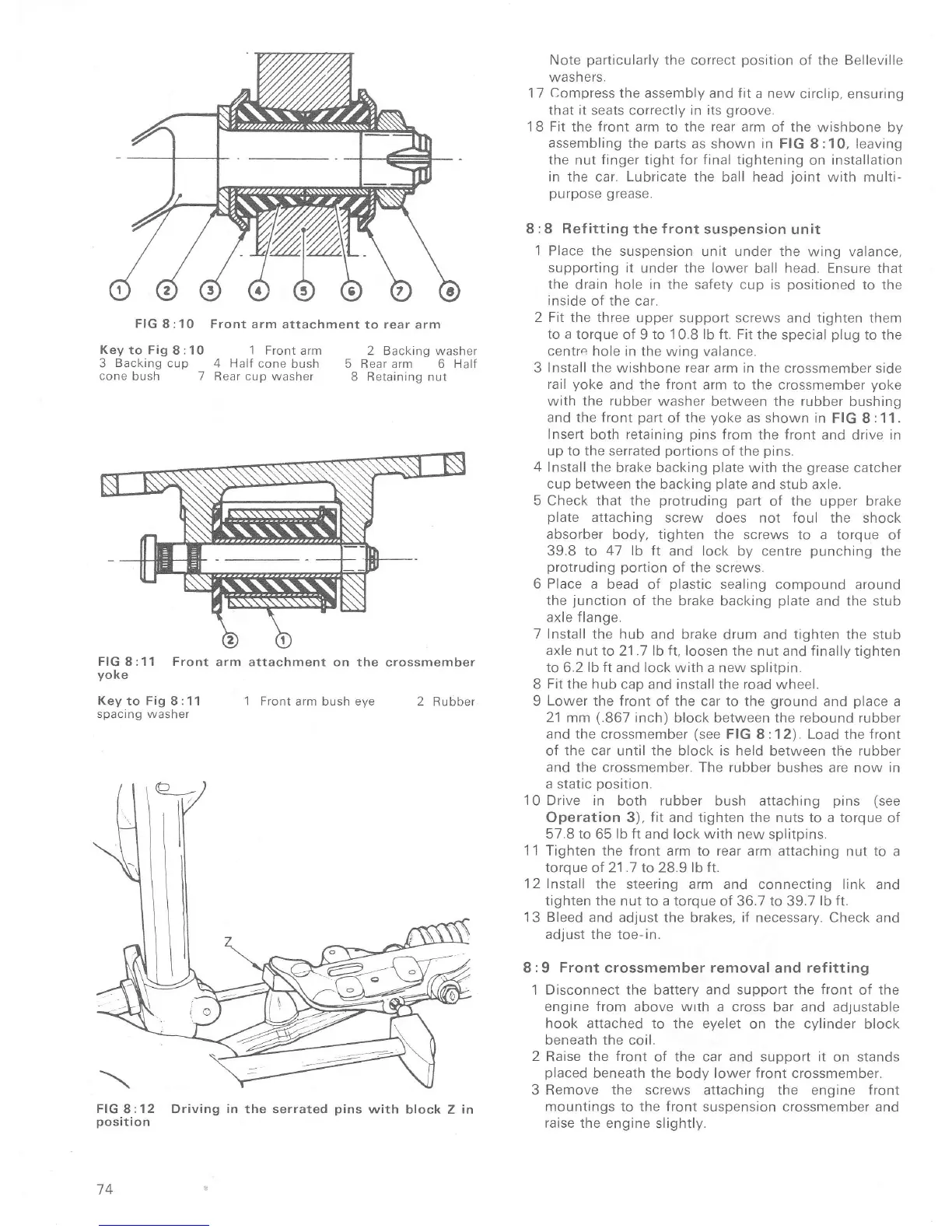
FIG
8 :1 0 Front arm
attachment to rear arm
Key
to Fig 8:1 0 1 FÍont
arm 2 Backing washer
3
Backing
cup 4 Half cone
bush 5 Rear arm 6 HalÍ
cone
bush 7 Rear cup washer
8 Retaining nut
Note
particularly
the correct
position
of the
Belleville
washers.
17
Compress
the
assembly and
f it
a new
circlip, ensuring
that it seats
correctly
in its
groove.
18 Fit the front arm to the rear arm
of the wishbone Lry
assembling
the
parts
as shown in FIG
8:10,
leaving
the nut Íinger tight for Íinal tightening
on
installation
in
the car. Lubricate the ball head
ioint
with multi-
purpose grease.
8:8 Ref itting the front
suspension unit
1
Place the suspension
unit under the wing valance,
supportrng
it under the lower
ball
head.
Ensure that
the
drain
hole in the saÍety
cup is
positioned
to the
inside
of the car.
2 Fit the three
upper support screws
and
tighten
them
to a torque
of 9
to 10.8 lb Ít. Fit
the special
plug
to the
centre hole in the
wing
valance.
3
Install the
wishbone rear arm in the crossmember
side
rail
yoke
and the front arm to the
crossmember
yoke
with the rubber
washer between the rubber
bushing
and the front
part
of
the
yoke
as shown in
FIG 8:11.
Insert both retaining
pins
from
the front and
drive
in
up to the serrated
portions
of the
pins.
4 Install the
bÍake backing
plate
with the
grease
catcher
cup
between the backing
plate
and
stub axle.
5 Check that the
protruding
part
oÍ
the upper brake
plate
attaching
screw
does
not foul the shock
absorber body, tighten the
scÍews to a torque oÍ
39.8 to 47 lb Íï
and
lock
by centre
punching
the
protruding portion
oí the screws.
6 Place
a bead
of
plastic
sealing compound
around
the
junction
of
the
brake backing
plate
and the stub
axle
Ílange,
7 Install the hub
and brake drum and tighten the stub
axle
nut ïo 21
.l
lb Ít, loosen the nut and finally
tighten
to
6.2
lb ft
and
lock
with a new splitpin.
I Fit the hub cap and install the road
wheel.
9
Lower
the íront
of
the car to the
ground
and
place
a
21 mm
(.867
inch)
block between the
rebound
ruboer
and the crossmember
(see
FIG 8 :12). Load the front
of
the car
until the block is held between the rubber
and the crossmember. The rubber
bushes are now
in
a
static
position.
l0Drive
in both rubber
bush
attaching
pins (see
Operation 3),
fit
and tighten the nuts to a torque
of
57.8 to
65
lb Ít and lock with
new splitpins.
1 1
Tighten the Íront arm to rear arm attaching
nut to a
toroue
of 21
.7
ro28.9 lbÍt.
12 Install
the steering arm and connecting link
and
tighten the
nut to a torque oÍ 36.7 to 39.7
lb Ít.
13 Bleed and adjust the brakes, iÍ necessary. Check
and
adjust the toe-in.
8:9 Front crossmember removal
and
ref itting
1 Disconnect the battery
and
support
the fÍont
oÍ
the
engine from
above
wrth
a cÍoss bar and adJustable
hook attached to the evelet
on the cvlinder block
beneath the
coil.
2
Raise the
front
oÍ the car and support it
on
stands
placed
beneath the body lower Íront crossmember.
3 Remove the screws attaching the engine front
mountings to the front
suspension crossmember and
raise the engine
slightly.
FIG
8:11
Front
arm attachment on the
yoke
crossmembeí
2 Rubber
Key
to Fig 8
:11
spacrng
washer
1 Front arm bush eye
FIG
8:12 Driving
in
the seÍrated
pins
with
block Z
in
position
74

 Loading...


