--r:
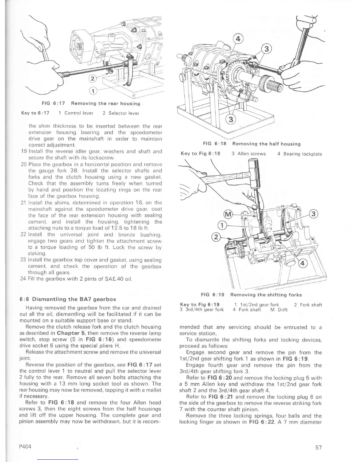
FIG 6:17 Removing
the
rear
housing
Kevto6:17 1 Controllever
2
Selectorlever
the
shim thickness to be inserted
between the rear
extension housing
bearing and the
speedometer
drive
gear
on
the mainshaft in
order to
maintarn
coÍrect
adlustment.
19 Install
the reverse idler
gear,
washers
and
shaft and
secure
the
shaÍt
with
its lockscrew.
20
Place
the
gearbox
in a
horrzontal
position
and remove
the
gauge
Íork 38.
Install
the
selectoí shafts
and
Íorks
and the clutch housing using a new
gasket.
Check that the assemblv turns Íreelv when turned
by
hand and
position
the locating
rings on
the rear
face
of
the
gearbox
housing.
21 Install the shims, determined
in
operation
18,
on the
mainshaÍt against
the
speedometer
drive
gear,
coat
the Íace
oÍ
the rear extension housing
with
sealing
cement, and
install the
housing,
tightening
the
attaching nuts to a torque load of 12.5 to 1B lb ft.
22
Instali the
universal
joint
and bronze bushing,
engage two
gears
and tighten the
attachment
screw
to
a torque loading
oÍ
50
lb ft. Lock the
screw by
slaKrng,
23 Install
the
gearbox
top cover
and
gasket,
usrng
sealing
cement,
and check the
operation oí the
gearbox
through
all
gears.
24 Fill
the
gearbox
with
2
pints
of
SAE.40 oil.
6 :6 Dismantling the BA7
gearbox
Having removed
the
gearbox
Írom the car and drained
out all the
oil,
dismantling will
be
facilitated if it
can be
mounted
on a suitable suppoÍt base
or
stand.
Remove
the clutch
release
fork and the clutch housing
as descÍibed in
Chapter 5,
then remove
the
reverse
lamp
switch, stop
screw
(5
in FIG
6:16) and speedometer
drive
socket 6 using the special
pliers
H.
Release
the
attachment screw and
remove
the universal
joint.
Reverse
the
position
of the
gearbox,
see
FIG
6
:1 7
set
the
control lever 1 to neutral
and oull the selector lever
2 fully
to the rear. Remove
all seven bolts attaching the
housing with
a 13
mm long
socket tool as shown. The
rear housing
may now be removed,
tapping
it with
a mallet
iÍ
necessary.
Refer
to
FIG
6:18 and
remove
the four Allen head
screws
3, then the eight screws from
the
halÍ housings
and liÍt
oÍf the upper housing. The
complete
gear
and
pinion
assembly may now be withdrawn,
but
it is recom-
P4O4
3 Allen screws
4 Bearing
lockplate
Key to Fig
6
:19
3
3rdl4th
gear
Íork
FIG
6:19 Bemoving the shifting
forks
1 lst/2nd
gear
Íork
2 Fork
shaft
4 Fork
shaft M DriÍt
mended
that any
servicing should be entrusted
to a
service station.
To
dismantle the
shiÍting
forks
and locking
devices,
pÍoceed
as follows:
Engage
second
gear
and
remove
the
pin
Írom
the
1st/2nd
geaÍ
shifting fork
1 as shown in FIG
6 :
'l
9.
Engage Íourth
gear
and
remove
the
pin
from the
3rdl4th
gear
shifting fork
3.
Refer to FIG
6 :20 and Íemove the locking
plug
5 with
a 5 mm Allen key
and withdraw the 1st/2nd
gear
foÍk
shaft
2
and the
3rd/4th
gear
shaft
4.
Refer to FIG
6:21 and remove the locking
plug
6 on
the side
of the
gearbox
to remove the reverse
stÍiking fork
7 with
the counter
shaÍt oinion.
Remove
the three locking
springs,
four
balls
and
the
locking finger
as shown in FIG
6:22. A7 mm
diameter
FIG
6
:18
Removing
the halÍ housing
Key to Fig
6
:1
8
^-7

 Loading...


