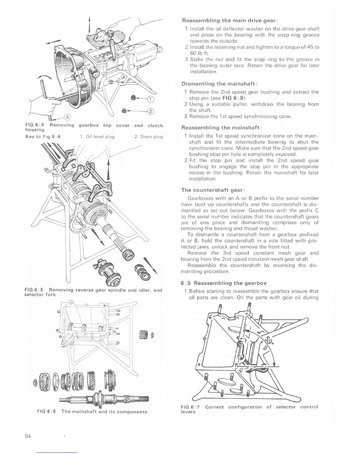
FlG6:4
Removing gearbox
top
cover
housi
ng
Key to
Fig
6:4
'l
Oil
level
plug
and clutch
2 Drain
plug
à
FIG
6:5 Removing reverse gear
spindle and idler,
and
selector fork
No
*@&
Reassembling the main drive
gear:
1
Install the oil
deflector
washer
on
the
drive
gear
shaft
and
press
on the bearing
with
the snap ring
groove
towards the
outside.
2 Install the retaining nut and tighten to a torque of
45
to
60 tb fr.
3
Stake
the nut
and
fit the
snap
ring to the
groove
in
the bearing outer
race.
Retain
the
drive
gear
for later
installation.
Dismantling
the mainshaft :
1
Remove the
2nd speed
gear
bushing
and
extract the
stop
pin
(see
FIG 6 :9).
2 Using
a suitable
puller,
withdraw the bearing from
the shaÍt.
3 Remove the
1
st speed synchronizing cone.
Reassembling the mainshaft
:
1 Install
the
1st
speed synchronizer
cone on the
main-
shaft
and fit the intermediate bearing
to
abut the
synchronizer
cone.
Make sure
that the 2nd speed
gear
bushing
stop
pin
hole is completely exposed.
2
Fit the
stop
pin
and
install
the 2nd speed
gear
bushing
to
engage
the
stop
pin
in the
appropriate
recess in
the
bushing.
Retain the
mainshaft for later
installation.
The countershaft
gear:
Gearboxes with
an A or
B
prefix
to the
serial
number
have built up countershaÍts and
the
countershaft is dis-
mantled
as set out
below. Gearboxes with the
orefix C
to the
serial
nurnber indicates that the countershaft
gears
are oÍ
one
piece
and dismantling comprises
only oÍ
removing the bearing
and
thrust washer.
To dismantle a countershaÍt
from
a
gearbox prefixed
A or
B,
hold
the
counteÍshaÍt in a
vice
fitted with
pro-
tected
jaws,
unlock
and remove
the Íront
nut.
Remove
the
3rd speed
constant mesh
gear
and
bearing from the 2nd
speed
constant mesh
gear
shaft.
Reassemble
the countershaÍt by reversing the dis-
mantlrng
procedure.
6
r5
Reassembling the
gearbox
1
Before
starting
to reassemble the
gearbox
ensure that
all
parts
are clean. Oil
the
parts
with
gear
oil during
CoÍrect configuration
oÍ selector
The mainshaÍt
and its
components
54
FIG 6:6
control

 Loading...


