7
Screw on a new ball head
housing,
tighten to a torque
oÍ
30
to 46 lb ft
and lock
by staking.
8 Install
the
pinion
ballbearing in
the rack
housing
and
fit the retaining
clip.
I
Fit
the flexible
coupling to the
pinion,
tighten
and
lock
the
bolts.
'1
0Insert the rack in
the housing
and
position
it
so that
the end
opposite the
ball
head
protrudes
by 98 mm
(3.846
inches)
as shown in FIG
g
:7.
11 Installthe
pinion,
fitted with
a new
O-ring sealso rhat
the
yoke
holes are
aligned
as shown in
FIG
9:7.
Fit
a
new
pinion
nut, tighten to a torque
of 11 to 14 lb ft
and
lock
by staking. Fit the housing
cap.
12 Refer to
Section 9:7 and determine the thickness
of
the
shims to be
inserted
between
the damper
Ílange
and the thrust
spacer of
the
damper, at the
pinion
end
oÍ the rack.
13 Install the rack
dampers and tighten the f lange
screws
to a torque of
7.25
to 9
lb
ft.
14 Check for
stiffness by operating the rack in
both
directions and Íit the rubber
boots,
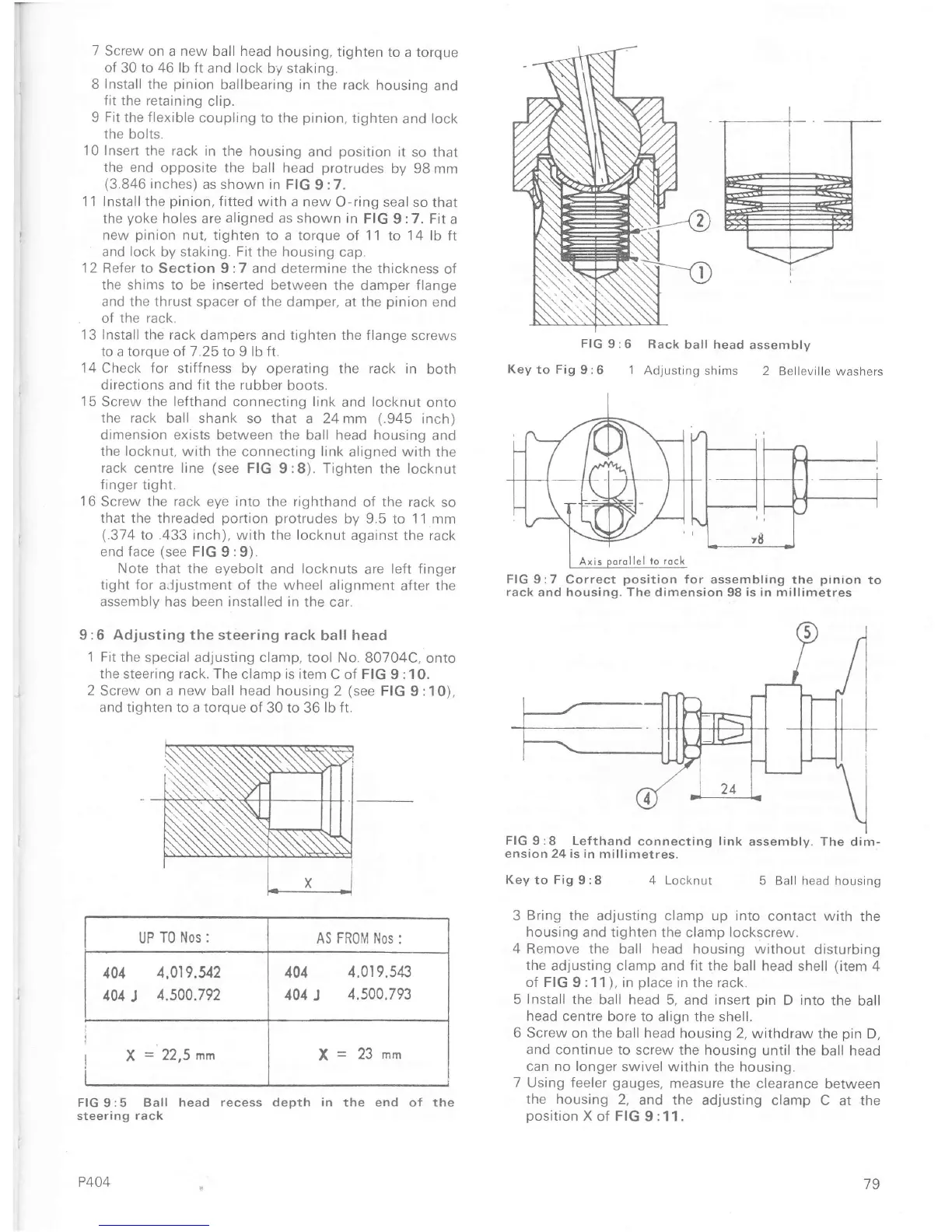
15
Screw ïhe
leÍthand
connecting ltnk
and
locknut
onto
the rack
ball shank so that
a 24mm
(.945
inch)
dimension exists between the
ball head housing and
the locknut,
with the connecting link
aligned
with
the
rack
centre
line
(see
FIG 9:8). Tighten
the
locknut
íinger
tight.
16
Screw
the rack
eye
into
the righthand
of
the rack
so
that
ïhe threaded
portion protrudes
by 9.5 to 1
'1
mm
(.374
to
.433 inch),
with the locknut
against the rack
end Íace
(see
FIG
9:9).
Note
that the eyebolt
and
locknuls
are
left finger
tight for
a.ljustment
of the wheel
alignment
after
the
assembly
has been
installed
in the
car.
9
:6
Adjusting the steering rack
ball
head
1 Fit
the special adjusting clanrp, tool No.
BO704C, onto
the steeÍing racl<. The clamp is item
C oÍ FIG
9
:10.
2
Screw on a new ball head housing
2
(see
FIG
9
:1
0),
and
tighten to a torque oÍ
30
to
36
lb fr.
FlG9:5 Ball head
recess depth in the end oÍ the
steering rack
P404
FIG
9:6 Rack
ball head
assembly
Key
to Fig
9:6 1
Adjusting
shims 2
Belleville washers
FIG 9:7 Correct
position
Íor
assembling the
pinion
to
rack and housing. The dimension 98 is in millimetres
FIG
9:8 Lefthand
connectinq
ension 24
is
in millimetres.
Key
to
Fig
I :8
;sembly. The
dim-
5 Ball head
housing
4 Locknut
3
Bring
the adjusting clamp
up
into
contact with
the
housing and tighten
the clamp
lockscrew.
4
Remove the ball head housing without
disturbing
the
adjusting clamp and fit the
ball
head
shell
(item
4
oÍ FIG
9
:1 1
),
in
place
in the rack.
5
Install
the ball head
5, and rnsert
pin
D into
the
ball
head centre
bore to align the shell.
6 Screw on the ball head
housing 2,
withdraw the
pin
D,
and
contrnue to screw
the housing until
the ball head
can no longer
swivel within the houstng.
7 Using feeler
gauges,
measure
the
clearance
between
the housing
2,
and the adjusting
clamp C at the
position
X oÍ FIG
9
:11
.
link
assemblv.
UP
T0 Nos :
AS FR0IVÍ Nos
:
401
4.01
9.543
101
J
4.s00.793
4.019.U2
4.500.792
79

 Loading...


