I
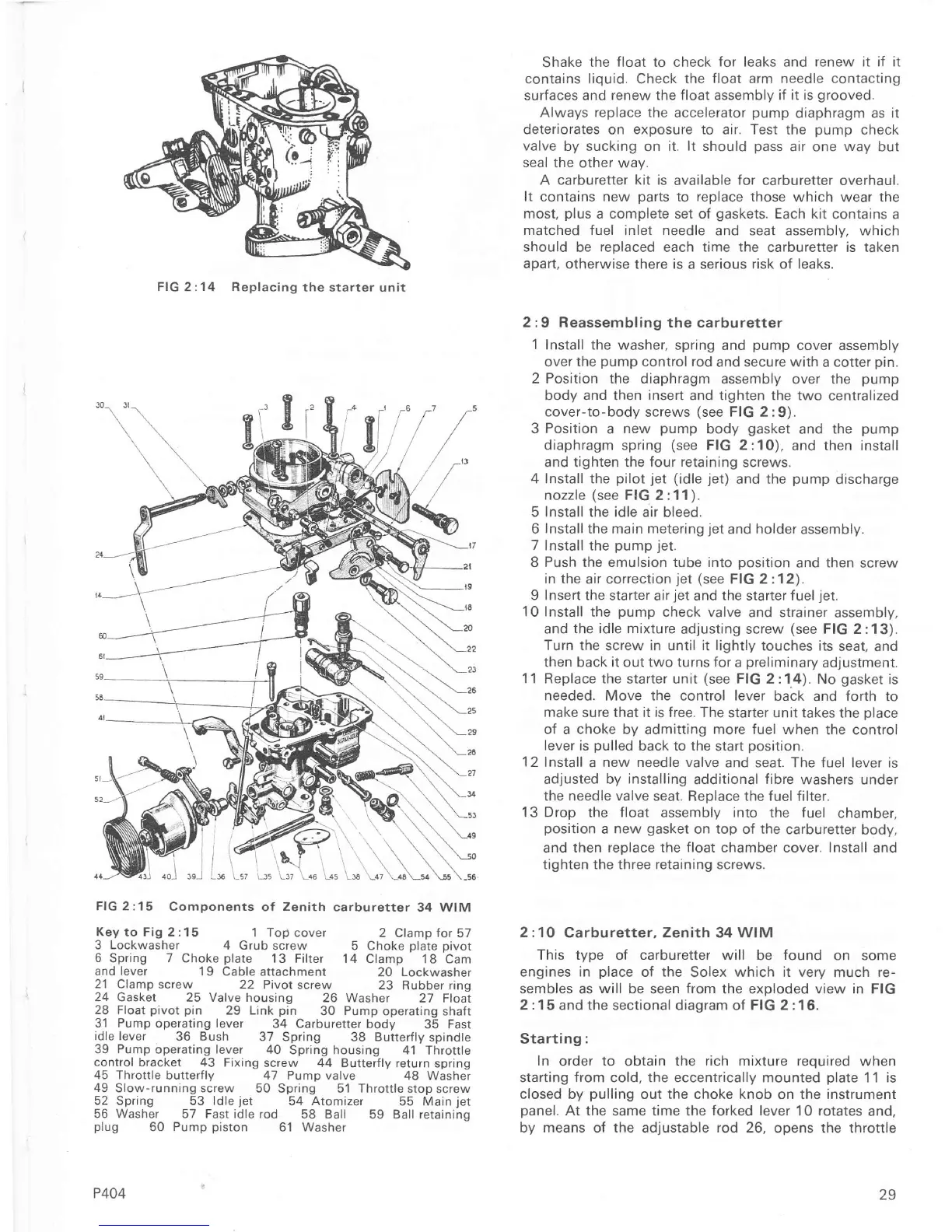
FIG 2:15
Components
of
Zenith
carburetter 34
WIM
Key
to Fig 2 : 1
5 1 Top
coveÍ 2 Clamp for
57
3 Lockwasher
4 Grub screw
5 Choke
plate
Divot
6
Spring
7
Choke
plare
13
Filter 14
Clamp 18 Cam
and leveÍ
1 9 Cable
attachment 20 Lockwasher
21
Clamp screw 22
Pivot scÍew 23
Rubber ring
24
Gasket 25 Valve housing
26 Washer
27 Float
28 Float
pivot pin
29
Link
pin
30
Pump
operating shaft
31 Pump
operating
lever
34 Carburetter body
35 Fast
idle lever
36 Bush
37 Spring
38
ButterÍly
spindte
39 Pump óperating lever
4O
Spring housing 41 Throtrle
control bracket 43
Fixing screw 44
ButterÍly return spring
45 Throttle butterfly 47 Pump
valve 48 Washer
49
Slow-running screw
50 Spring 51 ThÍottle stop screw
52
Spring 53 ldle
jet
54
Atomizer
55 Main
jet
56 Washer
57
Fast idle
rod 58 Ball
59
Ball retaining
plug
50
Pump
piston
61
Washer
P404
Shake
the float to check
for leaks and renew it iÍ it
contains liquid,
check
the float arm needle contacting
surÍaces and
renew
the
float assembly if it is
gÍooved.
Always replace
the accelerator
pump
diaphragm as
it
deterioÍates
on
exposure to
air. Test the
pump
check
valve
by sucking
on
it. lt should
pass
air one
way
but
seal the
otheÍ wav.
A carburetter kit is
available
for
carburetter overhaul.
It
contains new
parts
to
replace
those
which wear
the
most,
plus
a complete set oÍ
gaskets.
Each kit
contains a
matched fuel inlet needle
and seat assembly,
which
should be reDlaced each time the carburetter is taken
apart,
otheÍwise there is
a
seÍious risk of leaks.
2:9
Reassembling the carburetter
'1
Install the washeÍ,
spring and
pump
cover
assembly
over the
pump
control rod
and secure with a cotter
pin.
2 Position the diaphragm
assembly over the
pump
body and then
insert
and tighten the two
centralized
cover-to-body screws
(see
FIG 2:9)
3
Position
a
new
pump
body
gasket
diaphragm
spring
(see
FIG 2:10),
and tighten the Íour
retaining
screws.
4 Install the
pilot
jet
(idle
jet)
and the
pump
discharge
nozzle
(see
FIG
2:11).
5 Install the idle
air
bleed
6
Install
the main metering
jet
and
holder
assembly.
7
Install the
pump
jet.
8 Push the emulsion tube into
position
and
then
screw
in the
air correction
jet
(see
FIG 2:12).
9
Insert
the starter
air
jet
and
the starter fuel
jet.
10 Install
the
pump
check valve
and strainer
assembly,
and the idle
mixture
adjusting screw
(see
FIG 2:13).
Turn the
screw
in
until
it lightly
touches its
seat,
and
then back
it
out two turns for
a
preliminary
adjustment.
11
Replace
the
starter unit
(see
FIG
2 :1.4). No
gasket
is
needed.
Move
the
control
lever
back
and
forth
to
make sure that it is free. The
starter unit takes
the
place
of a choke by admitting more fuel
when the contÍol
lever
is
pulled
back to the
start
position.
12
Install
a
new needle valve
and
seat. ïhe fuel lever is
adjusted
by installing
additional
fibre
washers under
the needle valve
seat. Replace
the
fuel Íilter.
13 Drop
the
float
assembly into the fuel
chamber,
position
a new
gasket
on top of the
carburetter
body,
and
then reolace the float chamber cover. Install
and
tighten the three retaining screws.
2:10
Carburetter. Zenith 34 WIM
This type
of
carbuÍetteÍ will
be
found
on some
engines in
place
oÍ the
Solex
which it very
much
re-
sembles as
will
be seen
from
the exoloded view in FIG
2
:1
5 and the sectional diagram
oÍ
FIG 2 :1
6.
Starting:
In order to
obtain
the Íich mixture required
when
starting
from
cold,
the eccentrically
mounted
plate
11 is
closed by
pulling
out the choke knob on the instrument
panel.
At
the same time the
forked lever
10
rotates
and,
by
means
of the adjustable
rod
26, opens the throttle
\.T
and
the
pump
and then install
FIG
2:14 Replacing the
starter unit
f,
["
l6
29

 Loading...


