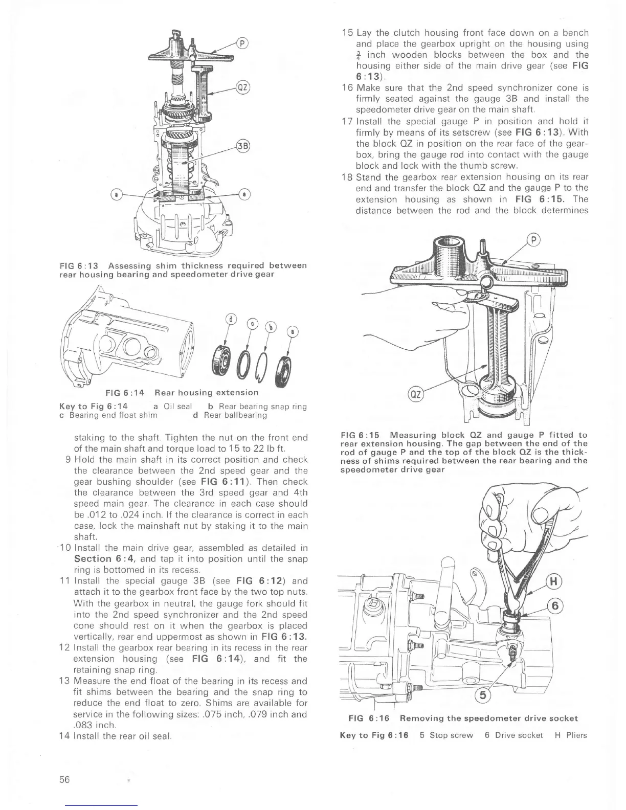
FIG 6:13
Assessing
shim
thickness
required between
rear housing bearing
and speedometer
drive
gear
15 Lay the clutch
housing
front face down
on
a bench
and
place
the
gearbox
upright on the housing using
f;
inch wooden
blocks between the
box and
the
housing either
side
of the
marn
drive
gear (see
FIG
6
: 13).
16
Make sure
that the 2nd
sDeed svnchronizer
cone is
firmly seated against
the
gauge
3B and
install the
speedometer
drive
gear
on the
main
shaft.
17Install the special
gauge
P in
position
and
hold it
firmly by means of its setscrew
(see
FIG
6:13).
With
the block OZ in
position
on
the rear face
of
the
gear-
box, bring
the
gauge
rod into contact with the
gauge
block and
lock with the thumb screw.
18
Stand
the
gearbox
rear
extension
housing on its rear
end
and transfer the
block OZ and the
gauge
P to the
extension
housing
as shown
in FIG 6
:15. The
distance
between the rod and the block determines
FIG
6:15
Measuring block OZ and
gauge
P fitted to
rear
extension
housing.
The
gap
between the
end
of
the
rod of
gauge
P
and the
top oÍ the block OZ
is
the thick-
ness of
shims
required
between the
rear bearing and the
speedometer
drive
gear
FIG 6 :1 6
Removing
the speedometer drive socket
KeytoFig6:16 5 Stopscrew
6 DÍivesocket H Pliers
Y ? P
p
@d
i
ó
FIG 6 :1
4 Rear housing
extension
Key to
Fig
6
: 1 4 a
Oil
seal
b Rear
bearing
snap
ring
c
Bearing end Íloat shim d
Rear
ballbearing
staking
to the
shaft.
Tighten the nut
on
the front end
oÍ the main shaft and torque load to
1
5 to 22 lb Ít.
9
Hold
the main shaft in its
correct
position
and check
the
clearance between
the
2nd speed
gear
and
the
gear
bushing
shoulder
(see
FIG 6:11). ïhen check
the clearance between the
3rd speed
gear
and
4th
speed main
gear.
The clearance in each case
should
be .O12 to .024 inch. lf the clearance
is correct in each
case, lock the
mainshaÍt nut by staking it
to
the main
shaÍ1.
10 Install the main drive
gear,
assembled as detailed in
Section
6:4, and tap it into
position
until the
snap
ring is bottomed in its recess.
11 Install the
special
gauge
3B
(see
FIG 6:12) and
attach it to the
gearbox
Íront Íace by the two top nuts.
With the
gearbox
in neutral, the
gauge
fork
should
Íit
Into
the 2nd
speed synchÍonizer
and the 2nd
speed
cone
should rest on it when the
gearbox
is
placed
veÍtically,
rear
end
uppermost
as shown
in FIG
6
:13.
12 lnstall
the
gearbox
rear bearrng in its recess in the rear
extension
housing
(see
FIG 6:14), and fit the
retaining
snap ring.
13 Measure
the end Íloat oÍ the bearing
in its
recess
and
fit
shims
between the
bearing and the snap ring
to
reduce the end Íloat to
zero,
Shims are
available Íor
service rn the following
sizes:
.075 inch, .079 inch and
.083
inch.
14 Install
the rear oil seal.
56

 Loading...


