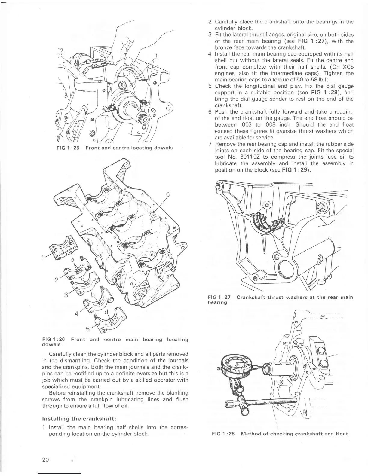
FIG 1:26 Front and
centre main bearing
locating
dowels
Caref ully clean the cylinder block and all
paÍts
removed
in
the dismantling.
Check the condition of the
journals
and
the crankpins. Both the main
journals
and the crank-
pins
can be
rectified
up
to a definite
oversize
but this is
a
job
which must be carried out by a skilled operator
with
specialized equipment.
BeÍore reinstalling the crankshaÍt,
remove
the blanking
screws from the crankpin
lubricating lines and flush
through to ensure a
full Ílow
of oil.
Installing the
crankshaft
:
1 Install
the
main
bearing
half
shells
into the corres-
ponding
location
on
the cylinder block.
20
CareÍully
place
the crankshaft onto the bearrngs in the
cylinder block.
Fit
the
lateral
thrust
Ílanges,
original size, on both sides
of the
rear main bearing
(see
FIG 1:27),
with the
bronze
face
towards the crankshaft.
Install the
rear
main bearing cap equipped with its half
shell
but
without the lateral seals. Fit the
centre and
front
cap
complete
with
their halÍ shells.
(On
XC5
engines, also
fit
the
intermediate
caps).
Tighten
the
main
bearing
caps to a torque of 50 to 58 lb ft.
Check
the
longitudinal end
play.
Fix the
dial
gauge
support in a suitable
position (see
FIG
1:28),
and
bring the dial
gauge
sender to rest on the end
of
the
crankshaft.
Push
the
crankshaft Íully forward and take a
reading
of
the
end
float
on
the
gauge.
The end
Íloat
should be
between
.003
to
.008 inch.
Should
the
end
float
exceed these
figures fit
oversize thrust
washers which
are available
for service.
Remove the
rear
bearing cap and
install
the
rubber
side
joints
on each
side oÍ the bearing cap.
Fit
the specia
tool No. 801102 to compress the
joints,
use oil to
lubricate
the assembly and
install the assembly in
position
on the block
(see
FIG 1 :29).
FIG 1 :27
Crankshaft
thrust
washers
at the
rear
main
bearing
\
FIG
1 :28
Method oÍ checking
crankshaÍt
end float
FIG
1 :25 Front and centre
locating
dowels

 Loading...


