FIG
9:9
Righthand cbnnecting
link eyebolt.
threaded
portion
should
protrude
9.5
to 11
mm
the
locknut when correctly
assembled.
Key to
Fig
9:9
4 Eyebolt locknut
6 Eyebolt
4 Fit the
damper
assembly, so
adjusted, to the
rack
housing
and
tighten the
Ílange
retaining
screws
to a
torque of 7.25 to
9 lb ft.
Adjustment shims
are available
in .10,..20 and
.50
mm sizes.
9:8 Connecting
link ball
joints
Dismantling:
l Hold the connecting
link in
a
vice
and
remove
the
crrclip
Írom
the
ball
head cap
(see
FIG 9
:1 3).
2 Remove
in the Íollowing order: ball
head cap
and
grease
nipple,4 Belleville
washers, nylon
half
bearing shell, ball
bolt and steel halÍ bearing
shell.
Beassembly:
1
Check and
renew
parts
where
necessary.
2 Install the
steel half bearing shell
in the bottom oÍ
the
ball
joint
housing.
3 ReÍer
to FIG
9:13
and
refit in the
following
order
the ball bolt,
nylon half bearing
shell, four
Belleville
washers
and the ball
head
cao.
4
Compress
the Belleville washers and
install
a
new
circlip
in the
gÍoove
above
the cap.
5 Position
the
ball head correctly with
the
pin
hole
in
the end of the ball bolt
at right angles to
the con-
necting
link axis. Lubricate the assembly.
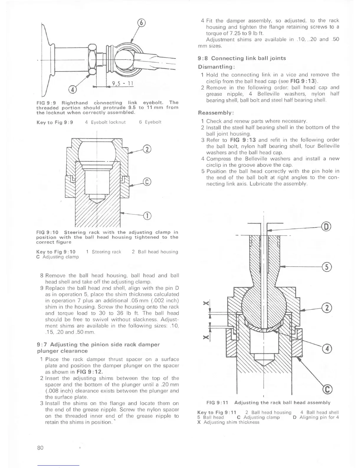
FIG 9 ;1 1 Adjusting the
rack
ball head assembly
Key to Fig 9:11 2
Ball head housing 4 Ball head shell
5
Ball head
C
Adjusting clamp
D
Aligning
pin
Íor 4
X
Adjusting
shim thickness
The
fro m
FIG
9:10 Steering
rack with
the adjusting clamp
in
position
with the ball head housing tightened to
the
correct
Íigure
Key to
Fig
9:10
1
Steering
rack
C
Adjusting clamp
2 Ball head housing
8
Remove the
ball
head housing, ball
head
and
ball
head shell
and
take oÍÍ
the
adjusting clamp.
9 Replace
the
ball
head and shell, align with the
pin
D
as in operation 5,
place
the shim thickness calculated
in
operation 7
plus
an
additional .05mm
(.002
inch)
shim in the housing.
Screw
the housing onto the
rack
and toroue
load
to 30 to 36
lb Í1.
The ball
head
should be free to swivel without slackness. Adjust-
ment shrms
are
available in the following sizes:
.10,
.15, .20
and
.50
mm.
9:7 Adjusting the
pinion
side
rack damper
plunger
clearance
'1
Place the Íack damper thrust spacer on a surface
plate
and
position
the damper
plunger
on the spacer
as shown
in FIG
9
:12.
2 Insert
the adjusting shims between
the top
of
the
spacer and
the
bottom
of the
plunger
until a .20 mm
(.008
inch)
clearance
exists
between
the
plunger
and
the surÍace Dlate.
3
Install the shims on the flange and
locate
them on
the
end
oÍ
the
grease
nipple. Screw
the
nylon spacer
on
the
threaded
inner end
of
the
grease
nipple to
retain
the shims
in
position.'
80

 Loading...