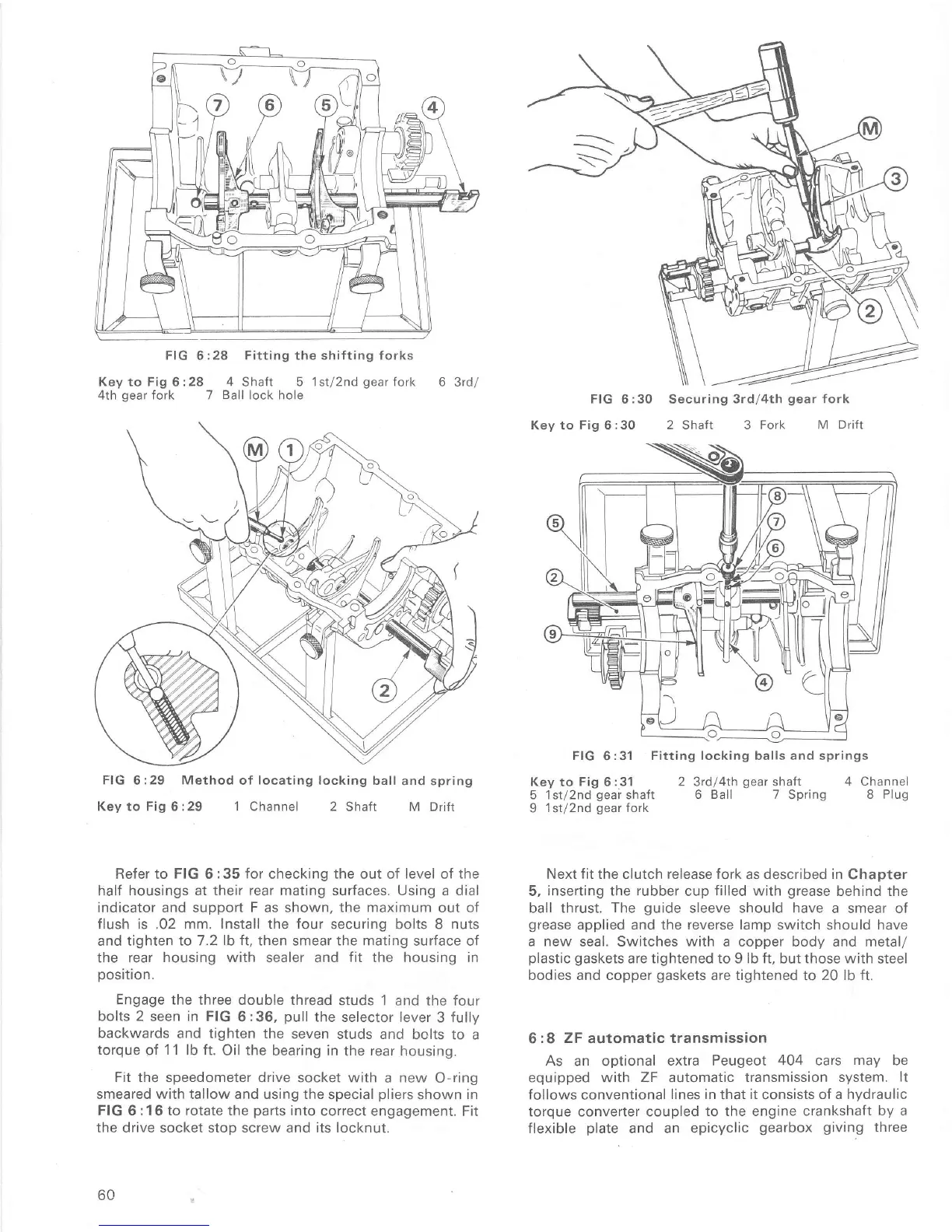
FIG 6 :28 Fitting the shiÍting forks
Key to Fig 6 :28 4 Shaft 5 1 st/2nd
gear
Íork
4th
gear
Íork 7
Ball
lock hole
6
3rd/
Key to Fig
6:29
1 Channel 2
Shafr M Drifi
Refer to
FIG
6:35
for
checking
the
out of
level
of
the
half housings at their Íear mating surfaces. Using a dial
indicator and support
F
as shown,
the maximum
out oÍ
flush is.02 mm.
Install the four
securing bolts 8
nuts
and tighten to 7 -2
lb ft,
then smear the mating surface of
the
rear housing with sealer and fit the housing in
position.
Engage the
three double thread
studs 1 and the Íour
bolts
2
seen in FIG
6:36,
pull
the selector lever
3 fully
backwards
and tighten the
seven studs and
bolts to a
torque
of
11
lb ft.
Oil
the
bearing in the rear
housing.
Fit
the speedometer drive socket with
a
new
O-ring
smeared with tallow and using the special
pliers
shown in
FIG 6:16 to rotate the
parts
into
correct engagement. Fit
the drive socket stop screw and its locknut.
60
Key
to
Fig
6
:30 2 Shaft 3 Fork M
DriÍt
FIG 6:31 Fitting locking balls and springs
Key to
Fig
6:31
2 3tdl4th
geaí
shaft
4 Channel
5 lsrl2nd
gear
shaft 6
Ball 7
Spring
8 Plug
9
1st/2nd
gear
fork
Next fit the clutch release fork
as
described in
Chapter
5,
inserting
the
rubber
cup
filled
with
grease
behind the
ball thrust.
The
guide
sleeve should
have
a smear of
grease
applied and the reverse lamp switch
should
have
a new
seal. Switches
with
a copper body and metal/
plastic
gaskets
aÍe tightened to 9 lb ft, but those with
steel
bodies and copper
gaskets
are tightened to 20 lb ft.
6:8
ZF
automatic
transmission
As an optional extra
Peugeot
404
cars
may
be
equipped with ZF automatic transmission
system.
lt
follows conventional
lines in
that
it
consists
of a hydraulic
torque converter coupled
to the engine crankshaft
by a
flexible
plate
and an epicyclic
gearbox
giving
three
FIG
6:29
Method
oÍ
locating
locking ball
and spring

 Loading...


