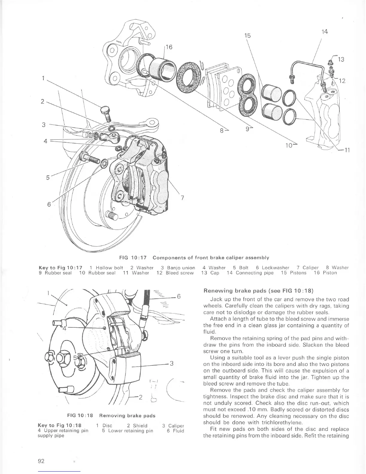
FIG 10:17
Components of
f ront
brake caliper assembly
KeytoFigl0:17
'lHollowbolt
2Washer
3Banjounion
4Washer SBolt 6Lockwasher
TCaliper 8Washer
9 Rubberseal 10 Rubberseal 11 Washer
'12
Bleed screw 13 Cap 14 Connecting
pipe
15 Pistons 16 Piston
FIG
10 : 18
Key to Fig 10 :
18
4
Upper retaining
pin
suppry
prpe
92
Removing
brake
pads
1 Disc
2 Shield
5
Lower
retaining
pin
3 Caliper
6 Fluid
Renewing brake
pads (see
FIG
10
:18)
Jack up
the Íront
of the caÍ and remove the two road
wheels. Carefully clean the
calipers with dry rags, taking
care not to dislodge
or damage the rubber seals.
Attach a
length
of tube to the
bleed screw and
immerse
the free
end
in
a clean
glass
jar
containing a
quantity
of
Ílu id.
Remove the retaining spÍing oÍ the
pad pins
and
with-
draw
the
pins
from
the
inboard
side.
Slacken
the
bleed
screw one turn.
Using a suitable tool as a lever
push
the single
piston
on the inboard
side
into its
bore and also the two oistons
on the outboaÍd side. This will
cause the expulsion of a
small
quantity
of brake fluid into
the
jar.
Tighten
up the
bleed screw and
remove
the tube.
Remove the
pads
and check the
calrper assembly
for
tightness. Inspect the brake
disc and make sure that it is
not unduly scored. Check
also the disc
run-out,
which
must not exceed .10 mm. Badlv
scored or distorted
discs
should be renewed. Any cleaning
necessary on the disc
should
be done
with
trichlorethylene.
Fit new
pads
on both sides of the disc and replace
the
retaining
pins
Írom the inboard
side. Refit the retaining

 Loading...


