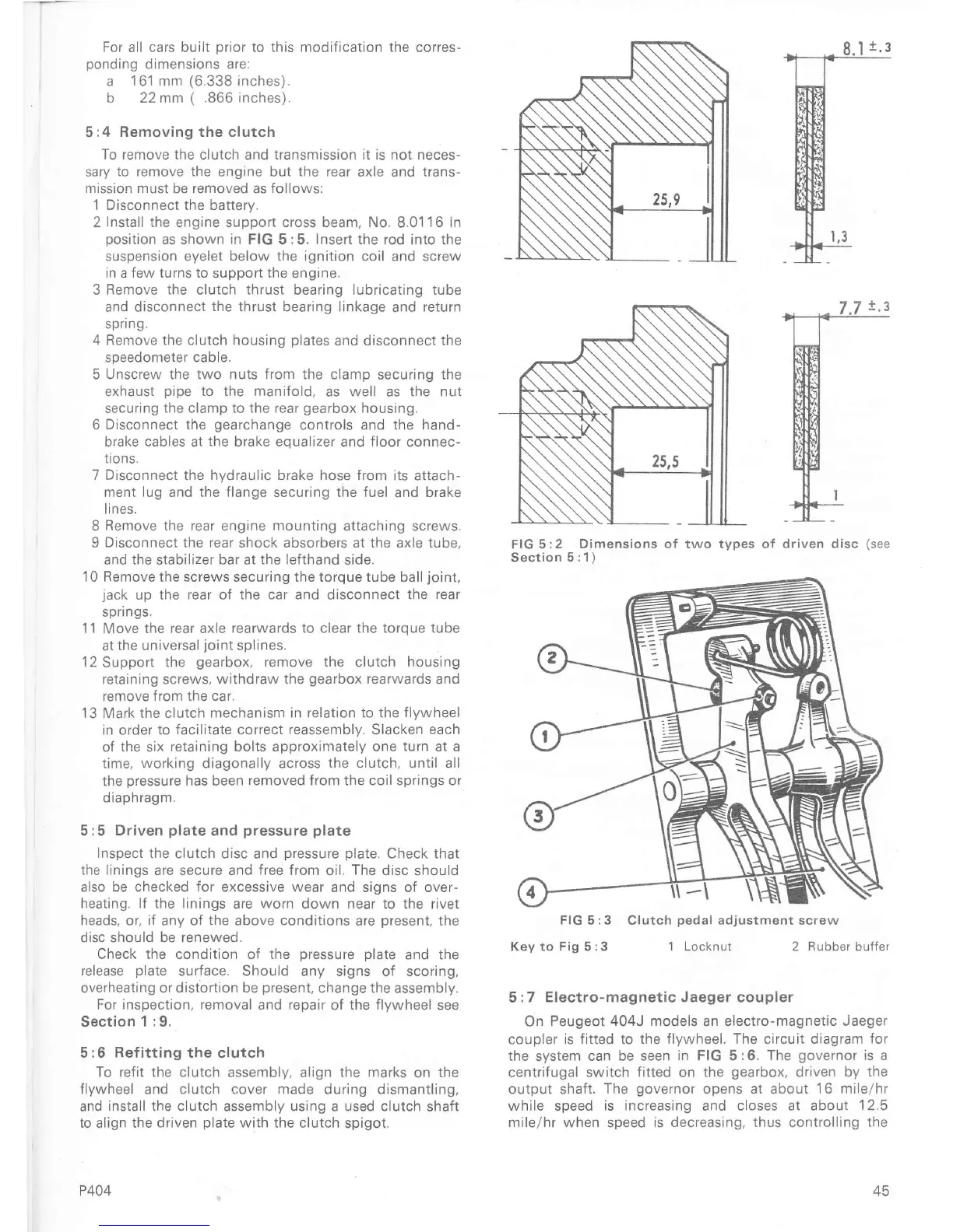
For all cars built
prior
to
this modification
the corres-
ponding
dimensions are:
a
161
mm
(6.338
inches).
b 22 mm
(
.866
inches).
5:4
Removing the clutch
To remove the
clutch and transmission it is not neces-
sary
to remove the
engine but
the
rear axle and trans-
missron must be removed as Íollows:
1 Disconnect the battery.
2Install
the
engine support cross beam, No.8.01
16In
position
as shown
in
FIG 5:5.
Insert the
rod into the
suspension eyelet below
the
ignition coil and screw
rn a few turns to
support
the
engine.
3 Remove
the
clutch thrust bearing lubricating tube
and disconnect
the
thrust bearing linkage
and
return
spring.
4
Remove the clutch housing
plates
and
disconnect the
speedometer
cable.
5
Unscrew the two nuts from the
clamp securing the
exhaust
pipe
to the manifold,
as
well
as
the
nut
securing the
clamp
to the
rear
gearbox
housing.
6
Djsconnect the
gearchange
controls and the hand-
brake
cables
at
the
brake
equalizer
and
Íloor
connec-
trons.
7 Disconnect the hydraulic brake hose
from its attach-
menr lug and the flange securing the fuel
and
brake
l r nes,
8
Remove the rear engine
mounting
attaching
screws.
9
Disconnect the rear
shock absorbers at the axle tube.
and
the
stabilizer bar at
the lefthand
side.
10 Remove the screws securing the torque tube ball
joint,
jack
up the
rear
of the
car and
disconnect
the rear
springs.
11
Move
the rear axle
rearwards to
cleaÍ
the torque tube
at
the universal
joint
splines,
l2Support the
gearbox,
remove
the
clutch
housing
retaining scÍews, withdraw
the
gearbox
rearwards
and
remove from the
car.
13 Mark the clutch mechanism
in relation to the flvwheel
in order to facilitate correct
reassembly,
Slacken
each
of the six retaining bolts
approximately one
turn
at a
time,
working
diagonally across
the clutch, until
all
the
pressure
has been removed Írom the coil springs or
diaphragm,
5:5 Driven
plate
and
pressure plate
Inspect the
clutch disc and
pressure plate.
Check that
the
linings
are secure and free from
oil.
The disc
should
also
be checked for excessive wear
and signs of over-
heating. lf the linings
are
worn
down near to the rivet
heads, or. iÍ any of the
above
conditions
are
present,
the
disc should be renewed,
Check the condition
of
the
pressure
Dlate and the
release
plate
surface, Should any signs
of scoring,
overheatrng or distortion be
present,
change the assembly.
For inspection, removal and repair
of
the flywheel
see
Section
1 :9.
5:6 Refitting the
clutch
To refit the clutch
assembly, align the
marks
on the
flywheel
and
clutch cover made
during dismantling,
and
install the clutch assembly using
a
used clutch
shaft
to
align
the driven
plate
with the clutch
spigot.
P404
FIG
5:2 Dimensions
of
two types of driven
disc
(see
Section
5 :1)
Key
to
Fig 5:3 1 Locknut 2 Rubber
buífer
5
:7 Electro-magnetic Jaeger coupler
On Peugeot
404J models
an
electro-magnetic Jaeger
coupler is
Íitted
to
the flywheel, The circuit diagram for
the
system
can be seen in
FIG
5:6.
The
governor
is a
centrifugal switch
fitted
on
the
gearbox,
driven by the
output shaft.
ïhe
governor
opens at about
16 mile/hr
while
speed
is increasing
and
closes at about
12.5
mile/hr when
speed
is decreasing, thus controlling the
FIG 5:3 Clutch
pedal
adjustment screw

 Loading...


