FIG 4:9
Checking the clearance
between the
front
face
of the impêller blades
and the rear face
of the
water
pump
body
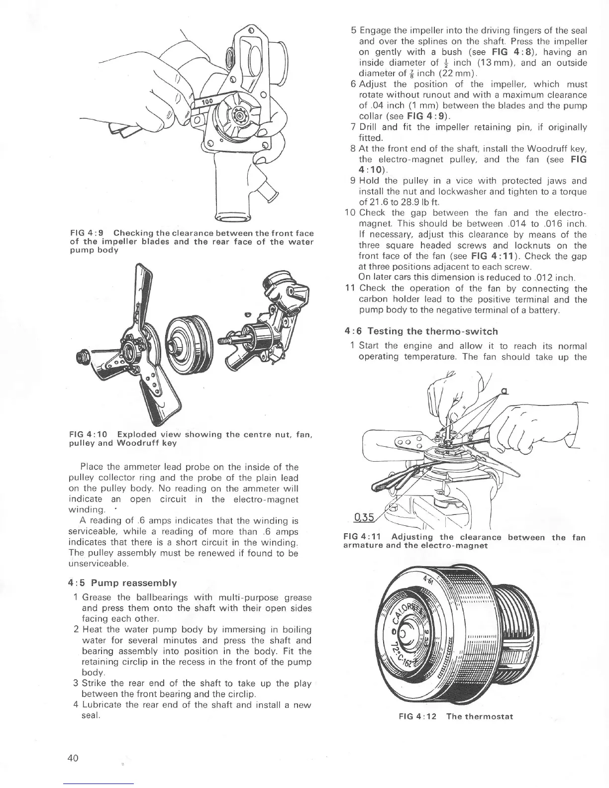
FIG
4:10 Exploded view showing
the centre nut, fan
pulley
and Woodruff key
Place
the ammeteÍ lead
probe
on the inside
of the
pulley
collector ring
and the
probe
oÍ
the
plain
lead
on the
pulley
body. No reading
on the
ammeter
will
indicate
an open circuit in the
electro-magnet
winding.
A
reading
of
.6
amps indicates that the winding
is
serviceable, while
a
reading
of
more
than .6
amps
rndicates
that there is
a short circuit in the winding.
The
pulley
assembly must be renewed if Íound
to be
unserviceable.
4:5 Pump reassembly
l Grease the
ballbearings
with
multi-purpose
grease
and
press
them
onto
the
shaft with their open
sides
facing
each other.
2 Heat the water
pump
body by
immersing
in boiling
water for
several minutes and oress the shaÍt and
bearing assembly into
position
in the
body.
Fit
the
retaining circlip in the recess in the
front of the
pump
body.
3 Strike the
Íear
end oÍ the shaft to take
up the
play
between the front
bearing and the circlip.
4 Lubricate
the rear end
of
the
shaÍt and install a new
sea
l.
40
5 Engage the impeller into the driving fingers
of
the
seal
and over the splines on the
shaft.
Press the impeller
on
gently
with a bush
(see
FIG 4:8), having
an
inside diameter
of
j
inch
(13
mm), and an outside
drameter of
{
inch
(22
mm)
.
6 Adjust the
position
of
the impeller, which
must
rotate without runout
and
with
a
maximum
clearance
of
.04
inch
(1
mm)
between the blades and the
pump
collar
(see
FIG 4:9).
7
Drill
and fit the impeller retaining
pin,
if originally
fitted.
8
At the front
end of
the
shaft, install the
Woodruff
kev,
the
electro-magnet
pulley,
and the
fan
(see
FIG
4:10).
9 Hold the
pulley
in
a
vice with
protected
jaws
and
install
the nut and lockwasher and tighten to a torque
of 21
.6
to 28.9 lb fr.
10
Check the
gap
between the Ían
and the electro-
magnet. This
should be
between
.014
to
.016 inch.
lÍ necessary,
adjust this cleaÍance
by means of the
three
square
headed
screws
and
locknuts
on the
front Íace
oÍ the fan
(see
FIG 4:11
).
Check the
gap
at three
positions
adjacent to
each screw.
On
later
cars this dimension
is reduced
to .0'1
2 inch
1 1
Check the
operation of the fan by
connecting the
carbon holder
lead to
the
positive
terminal
and the
pump
body to
the negative terminal
of a battery.
4:6
Testing
the thermo-switch
1
Start
the
engine and
allow it to reach its
normal
operating temperature.
The fan
should take up the
FlG4:11
Adjusting
the
clearance between
the
armature
and the electro-magnet
fan
FIG 4:12 The
thermostat

 Loading...


