Chapter 1 Getting Started
ViewStation FX/VS 4000 User’s Guide 10 www.polycom.com
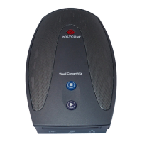
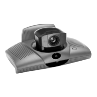
Figure 1-1. V.35 Network Interface Module (PLINK side)
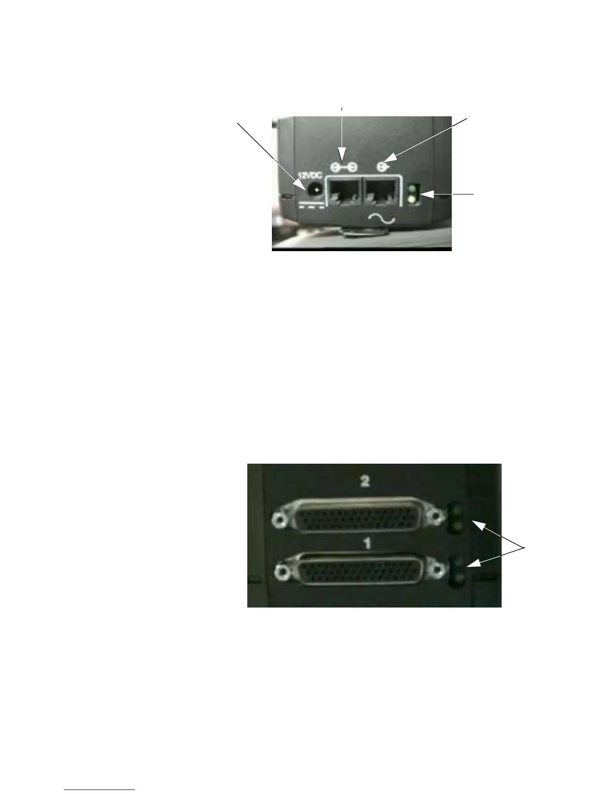
Connecting the V.35 Network Interface Module to the V.35
DCE
The back of the network interface module is where you connect to a
V.35 DCE. The V.35 network interface module contains two HD-44
female ports (labeled 1 and 2) that connect to data communications
equipment (DCE).
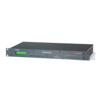
Figure 1-2 shows the NETWORK side of the V.35 network interface
module.
Figure 1-2. V.35 Network Interface Module (NETWORK side)
Note The ViewStation FX or VS4000 V.35 network interface
module is not interchangeable with the previous V.35
network interface module. The new module uses HD-44F
connectors (Ports 1 and 2), and uses a keyed RJ-45
12 VDC Connector
(not used)
Port (not used)
Input Port
LEDs
LEDs
 Loading...