Chapter 1 Getting Started
ViewStation FX/VS 4000 User’s Guide 12 www.polycom.com
7. Set the television monitor to Video 1 / 2, depending on which
inputs your ViewStation FX or VS4000 cables are connected to.
Note Some television monitors use different naming conventions
for the video in ports. Consult the users manual for the
television monitor for additional information on the video-in
ports.
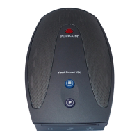
LED Activity on the Network Interface Module
To check your interface module connection, look at the LEDs next to
your DCE cable port.
PLINK Side Connection to the ViewStation FX or VS4000
The LEDs on the front of the interface module indicate the
connection status to the ViewStation FX or VS4000 (Figure 1-1).
When you power on the ViewStation FX or VS4000, the following
light sequence occurs:
1. Both LEDs flash once to indicate that the LED is working
properly.
2. The bottom amber LED glows solid to indicate that the
ViewStation FX or VS4000 is communicating with the network
interface module.
3. The top green LED glows solid to indicate that the ViewStation
FX or VS4000 is communicating with the network.
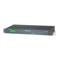
NETWORK Side Connecting to the V.35 DCE
Look at the LEDs next to your DCE cable ports to check your
network interface module connection (Figure 1-2).
 Loading...