Chapter 1 Getting Started
© Polycom, Inc. 13 ViewStation FX/VS 4000 User’s Guide
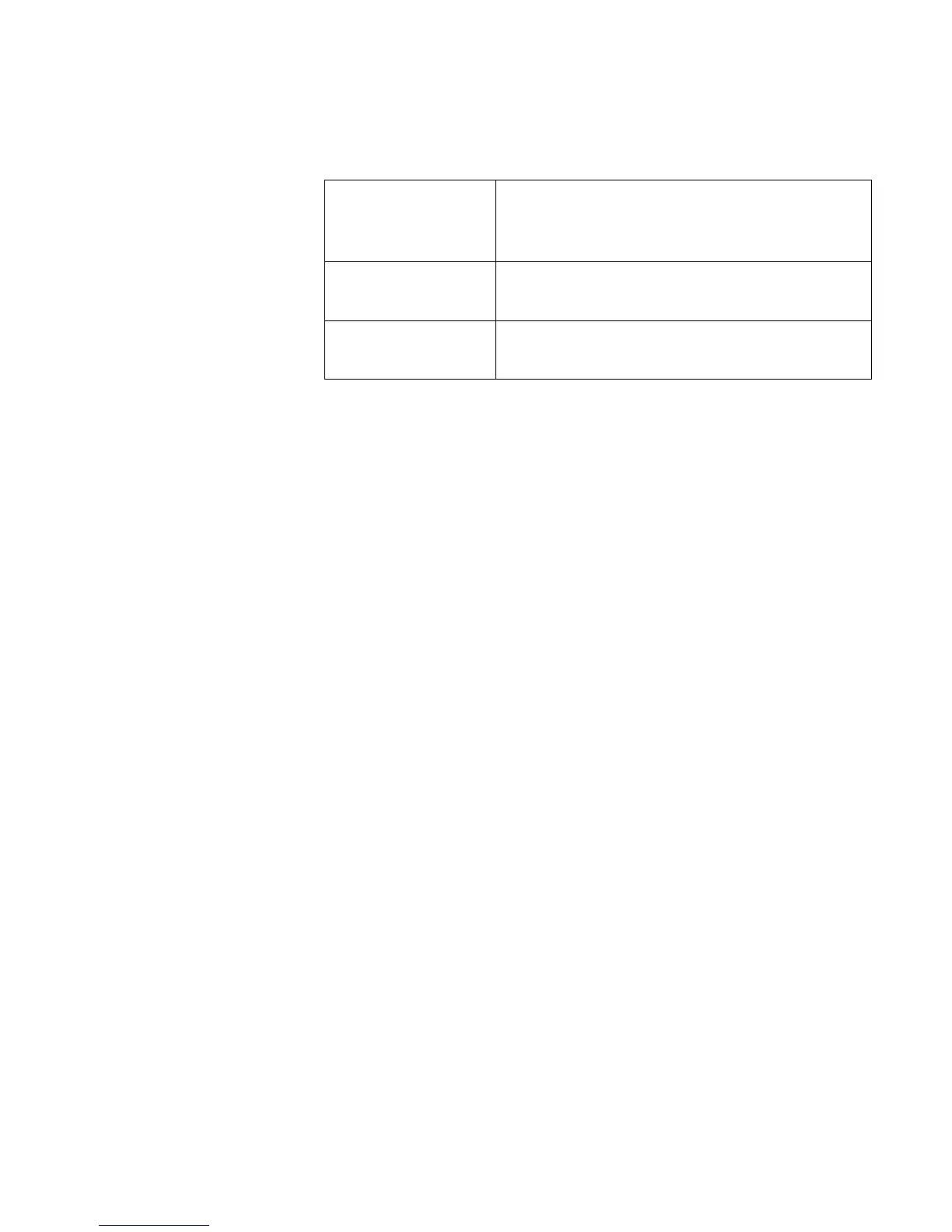
The top green LED corresponds to port status, and the bottom
amber LED corresponds to DCE clock status:
Once your interface is properly connected, you are ready to
configure your ViewStation FX or VS4000. See Initial System
Configuration.
PRI Network Interface Setup
The following information applies to both PRI E1 and the PRI T1.
The instructions explain how to connect the PRI network interface
module to your ViewStation FX or VS4000 system and how to
configure the PRI interface.
Connecting the PRI Network Interface Module
1. Power off your ViewStation FX or VS4000.
2. Plug the 12-volt DC power supply into the PRI network interface
module and then into the wall jack.
3. Find the cable with the light blue RJ-45 keyed connectors on
both ends.
4. Connect one end of the light blue keyed RJ-45 cable to the input
port on the back of the ViewStation FX or VS4000.
Figure 1-3 shows the peripheral link (PLINK) side of the PRI network
interface module that connects to the ViewStation FX or VS4000.
Solid amber LED
Indicates that a port is properly connected
to an active DCE and is receiving a
network clock.
Solid green LED
The ViewStation FX or VS4000 is in an
active call.
Green LED off
The ViewStation FX or VS4000 is not in a
call.
 Loading...