RL78/G10 CHAPTER 6 TIMER ARRAY UNIT
R01UH0384EJ0311 Rev. 3.11 143
Dec 22, 2016
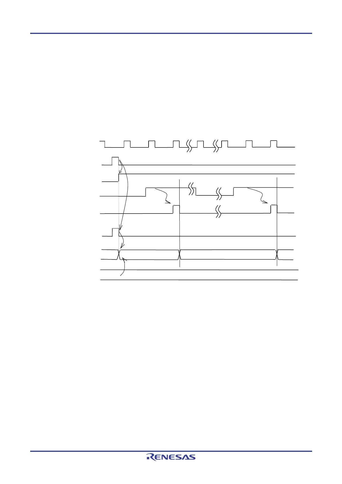
(2) Event counter mode operation
<1> Timer count register 0n (TCR0n) holds its initial value while operation is stopped (TE0n = 0).
<2> Operation is enabled (TE0n = 1) by writing 1 to the TS0n bit.
<3> As soon as 1 has been written to the TS0n bit and 1 has been set to the TE0n bit, the value of timer data
register 0n (TDR0n) is loaded to the TCR0n register to start counting.
<4> After that, the TCR0n register value is counted down according to the count clock (f
TCLK) of the valid edge
of the TI0n input.
Figure 6-25. Operation Timing (In Event Counter Mode)
Remark Figure 6-25 shows the timing when the noise filter is not used. When the noise filter is on-state, the edge
detection is delayed by two cycles of the operating clock (f
MCK) from the TI0n input (totally 3 to 4 cycles).
The error of one cycle is due to the asynchronous timing between the TI0n input and operating clock
(f
MCK).
fMCK
TS0n (Write)
TE0n
TI0n input
<1>
<2>
Count clock (fTCLK)
Edge detection
Edge detection
<4>
m
TCR0n
Initial
value
m
m−1
m−2
TDR0n
<3>
Start trigge
detection signal
<1>
<3>

 Loading...


