RL78/G10 CHAPTER 6 TIMER ARRAY UNIT
R01UH0384EJ0311 Rev. 3.11 144
Dec 22, 2016
(3) Capture mode operation (input pulse interval measurement)
<1> Operation is enabled (TE0n = 1) by writing 1 to the TS0n bit.
<2> Timer count register 0n (TCR0n) holds the initial value until count clock (f
TCLK) generation.
<3> A start trigger is generated at the first count clock after operation is enabled. And the value of 0000H is
loaded to the TCR0n register and counting starts in the capture mode. (When the MD0n0 bit is set to 1,
INTTM0n is generated by the start trigger.)
<4> On detection of the valid edge of the TI0n input, the value of the TCR0n register is captured to timer data
register 0n (TDR0n) and the interrupt request signal (INTTM0n) is generated. However, this capture value
has no meaning. The TCR0n register keeps on counting from 0000H.
<5> On next detection of the valid edge of the TI0n input, the value of the TCR0n register is captured to the
TDR0n register and the interrupt request signal (INTTM0n) is generated.
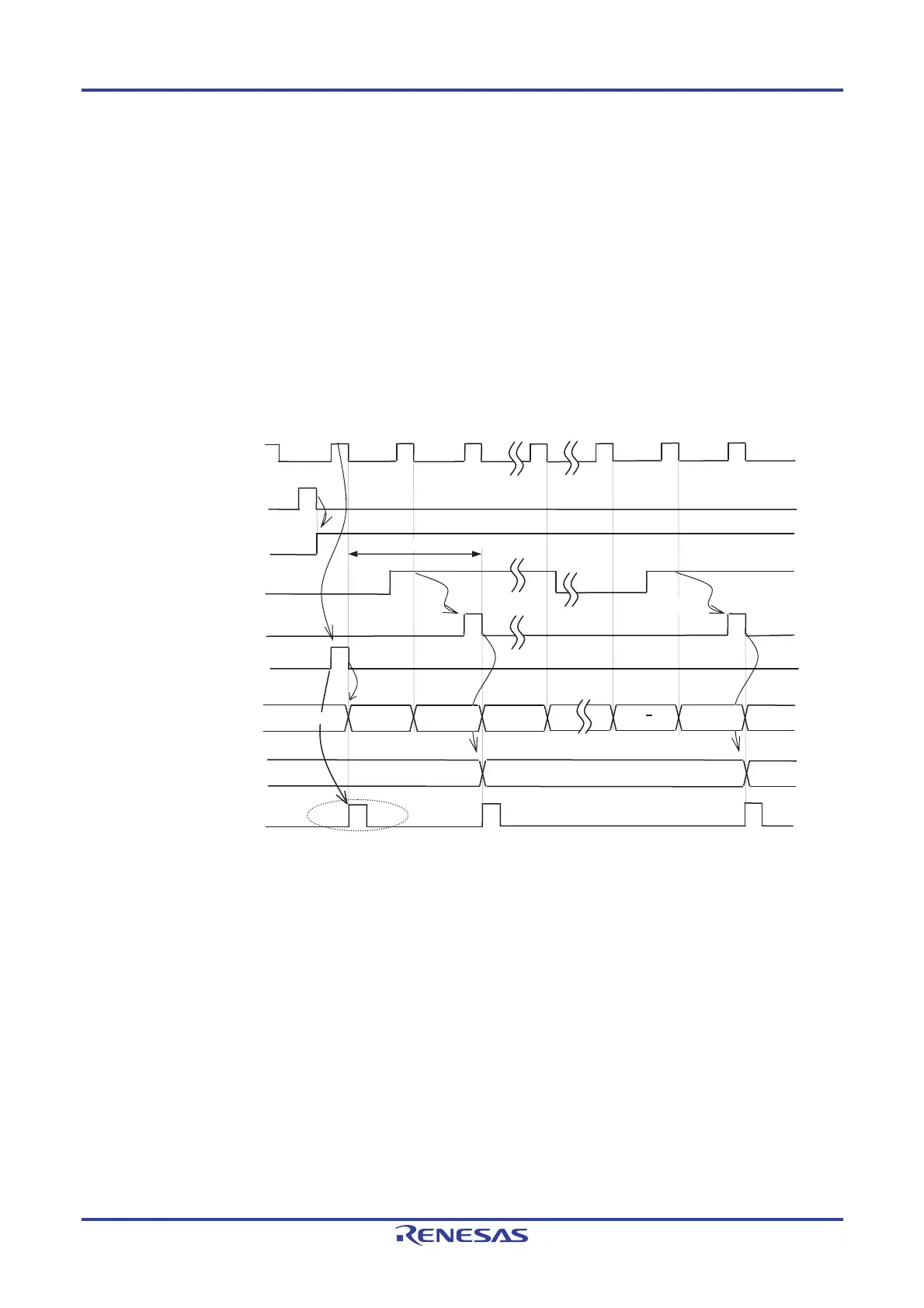
Figure 6-26. Operation Timing (In Capture Mode: Input Pulse Interval Measurement)
f
MC
(f
TCLK
)
TS0n (Write)
TE0n
TI0n input
<1>
<2>
Rising edge
<4>
TCR0n
m1
m
TDR0n
Start trigger
detection signal
<3>
0000
m
Edge detection
0001
0000
INTTM0n
<5>
0000 0001
<3>
Edge detection
Note
When MD0n0 is set to 1
Note
Initial value
Note If a clock has been input to TI0n (the trigger exists) when capturing starts, counting starts when a start
trigger is generated (<3>) by writing to TS0n (<1>), even if no edge is detected. Therefore, the first
captured value (<4>) does not determine a pulse interval (in the above figure, 0001 just indicates two clock
cycles but does not determine the pulse interval) and so the user can ignore it.
Caution In the first cycle operation of count clock (f
TCLK) after writing the TS0n bit, an error of a maximum
of one cycle of the count clock (f
TCLK) is generated since count start delays until count clock
(fTCLK) has been generated. When the information on count start timing is necessary, the interrupt
request signal (INTTM0n) can be generated at count start by setting MD0n0 = 1.
Remark Figure 6-26 shows the timing when the noise filter is not used. When the noise filter is on-state, the edge
detection is delayed by two cycles of the operating clock (fMCK) from the TI0n input (totally 3 to 4 cycles).
The error of one cycle is due to the asynchronous timing between the TI0n input and operating clock
(f
MCK).
 Loading...


