Do you have a question about the Ricoh A172 and is the answer not in the manual?
| Brand | Ricoh |
|---|---|
| Model | A172 |
| Category | All in One Printer |
| Language | English |
Details the various components and their configurations for the A172/A199 series.
Outlines the technical specifications, including resolution, paper handling, and speeds.
Provides a diagram and list of mechanical components within the main machine.
Illustrates the layout of the drive mechanisms and their components.
Details the electrical components, including PCBs, motors, and sensors.
Highlights key differences between the A172/A199 and the base copier (A109).
Explains the internal processes that control image formation and quality.
Covers the drum's function, charge, cleaning, and lubrication mechanisms.
Outlines the steps and components involved in image processing.
Covers the development section, including sleeve cleaning procedures.
Describes the toner tank's agitation and end detection mechanisms.
Explains the transfer belt's bias control and lubrication systems.
Covers the transfer belt/roller heater control and bias settings.
Details the fusing unit's roller cleaning mechanisms and temperature control.
Describes the operation panel's LCD, touch panel, and control block diagram.
Specifies the environmental, level, space, and power conditions for installation.
Covers accessory checks and installation procedures for the main copier unit.
Details the accessory check and installation procedure for the Dual Job Feeder.
Covers accessory check and installation procedure for the Sorter unit.
Details accessory check and installation procedure for the Film Projector unit.
Covers accessory check and installation procedure for the Controller Interface.
Explains how to access and operate the Service Program (SP) mode.
Provides a table of adjustable service program items and their functions.
Describes the Self-Diagnostic Test modes for checking system functions.
Explains how to output diagnostic data from various system components.
Details special features and settings accessible via SP mode.
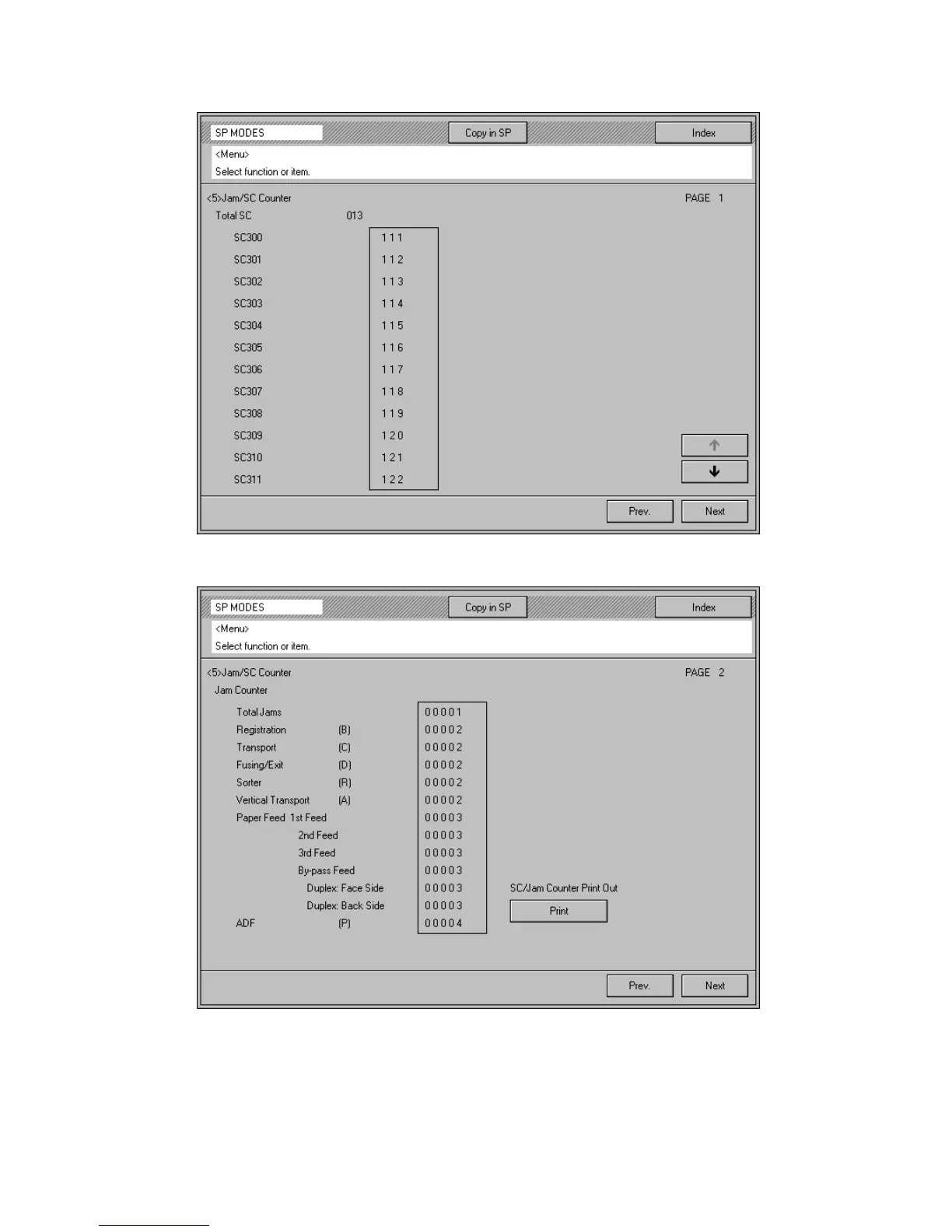
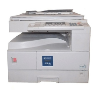
Explains how to view and print jam and service call counters.
Provides instructions for clearing various counters within the service program.
Identifies key test points, DIP switches, and LEDs on the main boards.
Outlines the recommended maintenance tasks and intervals for the machine.
Procedures for adjusting color balance and performing auto calibration.
Safety warnings and procedures related to the laser unit.
Procedures for replacing components of the drum unit.
Procedures for collecting and installing developer materials.
Procedures for replacing the belt lubricant bar and solenoid.
Covers the replacement of the roller lubricant bar.
Details the fusing unit's roller cleaning mechanisms and temperature control.
Procedures for replacing other components like fan filters and operation panel boards.
Guide for adjusting printer gamma settings with Fiery XJ controller.
Explains the different levels of service call conditions and their definitions.
Lists SC codes and possible causes related to scanner malfunctions.
Lists SC codes and possible causes related to printing subsystem issues.
Lists SC codes and possible causes related to the development unit.
Lists SC codes and possible causes related to the drum and associated components.
Lists SC codes and possible causes related to transfer belt and roller issues.
Lists SC codes and possible causes related to paper feed mechanism errors.
Lists SC codes and possible causes related to fusing unit temperature errors.
Lists SC codes and possible causes related to communication errors between boards.
Identifies fuses, their ratings, and symptoms of blown fuses.
Explains the self-diagnostic tests available for the operation panel.
Summarizes common problems detected during tests and identifies suspected faulty units.
Procedure for calibrating color balance using the glass-top copier.
Procedure for adjusting printer gamma settings with the Fiery XJ controller.
Updates related to the Operation Panel and Optics Section parts.
Updates related to the Fusing Unit components.
Updates related to the Pressure Spring component.
Lists the pages that require replacement with updated information.
Addresses an operation counter error after ROM upgrades.
Details issues with dirty backgrounds on copies due to specific ROM revisions.
Describes blurred images in black/white ACS mode linked to specific ROM revisions.
Addresses blank margins in single color mode caused by incorrect timing programs.
Explains the reason for modifying the Vcnt correction settings for toner density.
Describes installing 'F' version software on the Main Board for SC321 errors.
Notes that 'F' version software is installed during production.
Details how to obtain the 'F' version software ROM Kit (A172ROMF).
Adds a drawing for the Operation Panel Harness - IPU 1 to the parts catalog.
Procedure for calibrating color balance using the glass-top copier.
Procedure for adjusting printer gamma settings with Fiery XJ controller.
Explains the reason for modifying the Vcnt correction settings for toner density.
Describes installing 'F' version software on the Main Board for SC321 errors.
Notes that 'F' version software is installed during production.
Details how to obtain the 'F' version software ROM Kit (A172ROMF).
Updates related to the Operation Panel and Optics Section parts.
Updates related to the Transfer Roller Unit.
Updates related to the Pressure Spring component.
Lists affected units and serial numbers for IPU board ROM changes.
Corrects part number for Entrance Seal Belt Cleaning Unit.
Adds Toner Tank Unit part number to the Parts Catalog.
Lists the categories of service tips provided for troubleshooting.
Provides a procedure to address light copy quality issues.
Corrects the part number for the Entrance Seal Belt Cleaning Unit.
Adds the Toner Tank Unit part number to the Parts Catalog.
Lists the pages that require replacement with updated information.
Addresses an operation counter error after ROM upgrades.
Details issues with dirty backgrounds on copies due to specific ROM revisions.
Describes blurred images in black/white ACS mode linked to specific ROM revisions.
Addresses blank margins in single color mode caused by incorrect timing programs.
Corrects the part number for the Entrance Seal Belt Cleaning Unit.
Adds the Toner Tank Unit part number to the Parts Catalog.
Steps to prepare the machine before adjusting magenta toner scattering.