2. PROCESS CONTROL
2.1 LATENT IMAGE CONTROL
2.1.1 DRUM POTENTIAL SENSOR CALIBRATION
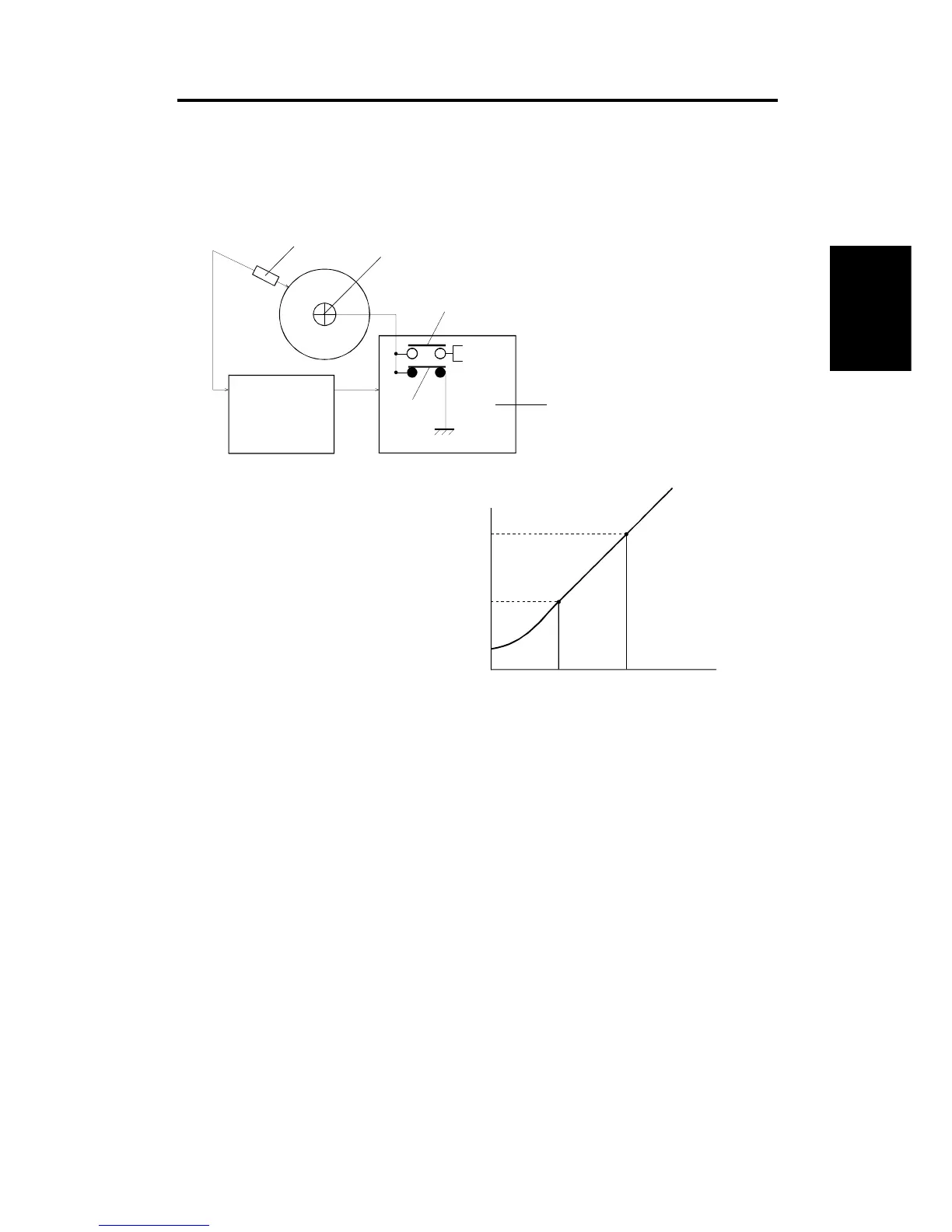
The drum potential sensor [A] output is calibrated during the process control
self check.
The High Voltage Supply Board - B [B] has two relay contacts. Usually RA
#1 grounds the drum. However, during the self check, the main CPU turns
RA #2 on and RA #1 off and applies the test voltage to the drum shaft [C]. In
this condition, the drum is isolated from the ground (floating).
By measuring the output of the drum potential sensor when –300 V (V
300
) or
–600 V (V
600
) are applied to the drum, the sensor output is calibrated
automatically. (The machine can now determine the actual drum potential
from the potential sensor output.) Using -300 and -600 V results in a more
accurate calibration of the sensor, since the voltage applied to the supply
board is much closer to the actual value, which is –450 V for V
B
(Development bias) during the process control self check.
Main Board
–300 V
–600 V
[A]
[C]
RA #2
RA #1
[B]
RA#1 and RA #2 are contained in RL1
on the High Voltage Supply Board – B.
Sensor Output
Actual Volta

 Loading...