Publication 2094-UM001A-EN-P — September 2006
Connecting the Kinetix 6000 Drive System 109
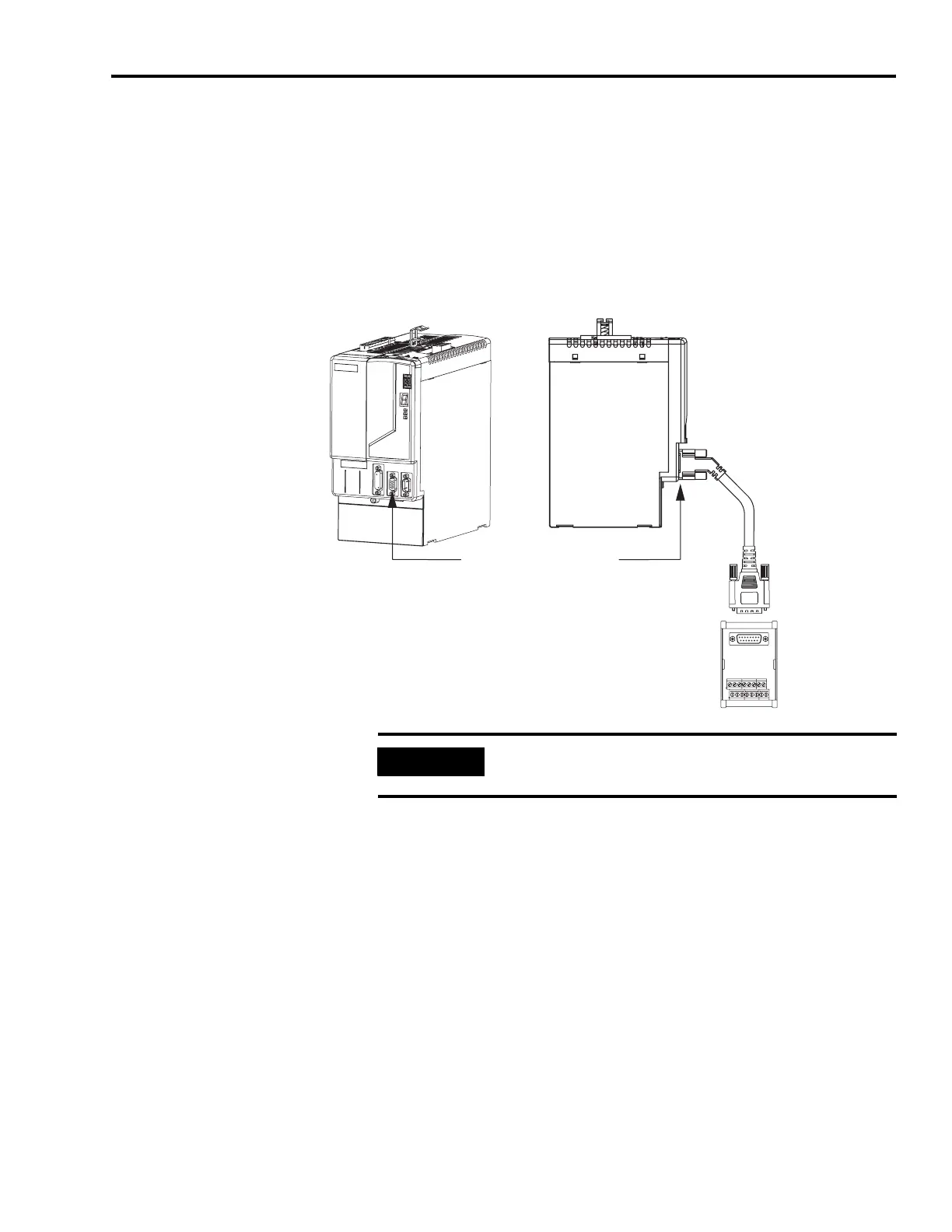
Wiring Panel-mounted Breakout Board Kits
The panel-mounted breakout board kit (catalog number
2090-UXBK-D15xx) includes a (DIN rail) breakout board and cable.
The cable connects between the breakout board and the motor
feedback (MF) connector. Wires from your flying-lead motor feedback
cable connect to the terminals.
Integrated Axis Module/Axis Module (MF connector)
Integrated Axis Module, Front View
(2094-BC02-M02-S is shown)
Motor Feedback (MF) Connector
Integrated Axis Module, Side View
(2094-BC02-M02-S is shown)
2090-UXBB-D15
Panel-mounted Breakout Board
Wire Terminations
2090-UXBC-D15
xx
Breakout Cable
IMPORTANT
The panel-mounted breakout board kit (2090-UXBK-D15xx) is
not compatible with 1326-CCUx-xxx cable.

 Loading...


